Electro Tech is an online community (with over 170,000 members) who enjoy talking about and building electronic circuits, projects and gadgets. To participate you need to register. Registration is free. Click here to register now.
Welcome to our site! Electro Tech is an online community (with over 170,000 members) who enjoy talking about and building electronic circuits, projects and gadgets. To participate you need to register. Registration is free. Click here to register now.
I really need help on this. I have to make a two player tic-tac-toe game using a breadboard and combinational logic etc.....i don't have a clue!
PLEASE HELP!!!
If you really wanted, you wouldn't need combinational logic at all. If red switch 1 is on, turn on red LED 1. If green switch 7 is on, turn on green LED 7. You get the idea. There's no error checking, but it does the job. ^^ You'd need 18 LEDs and 18 switches or buttons. Simple as that.
Starting at this barebones approach, we can try to make it more elegant. One thing you could do would be to use red/green bi-colored LEDs, to cut down on the physical 'bulbs' you have to look at. You could also cut down the switches to 9 by having it automatically keep track of whose turn it is. Start out with the first switch being turned on controlling a red LED. The next switch will automatically control a green LED. You could do that with a simple counter to keep track of the turns. You could use a 7490 decade counter for that, and use its least significant bit to determine red or green. When the counter hits 9, there's no more moves, so don't accept anymore input, except for a reset.
As for determining whether a move is valid, use a 2-input AND gate. Connect the LED to an inverter, and AND that with the switch. If either red/green LED is already on, then a 0 appears on the AND and nothing happens. If the LEDs were both was off, then the AND will turn current player's LED on. You may need additional gates to determine:
Code:
LED 1 green is OFF
LED 1 red is OFF
Switch 1 turned ON
It's red's turn
Therefore, turn on red LED 1.
or
Code:
LED 4 green is OFF
LED 4 red is OFF
Switch 4 turned ON
It's green's turn
Therefore, turn on green LED 4.
As for determining a winner, a bunch of 3 input AND gates is all that's needed. Figuring out a winner of 3-in-a-row game with 3 input AND gates should be pretty obvious. 8) Turn on a "red is the winner" or "green wins" indicator somewhere and stop accepting inputs. Fair warning, this method is going to be a big gob of wires! You might (hopefully) come up with a more efficient method for doing everything, but this should get you started. Good luck debugging that many gates and wires on a breadboard in lab. :roll:
Must it use combinational logic chips? Is this a requirement for a lab project? If its just something you're throwing together for your personal use, would you consider a cheapie $12 PIC programmer, and get free PIC samples from Microchip, Inc?
Yeah,it's a class project and unfortunately we have to use what we've learned in class i.e. combinational logic....however i am a dumbass and i don't get the whole circuit design thing so i have resorted to this site...i have 2 weeks to do the project....i've already wasted 2 weeks doing nothing so please help a dumbass(me).
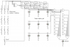
Well, here's the "I'm using the most amount of parts possible, do I win a prize?" approach that -might- work. I haven't done a walkthrough to see if it actually does, but the diagram seems sound. Forgive the MS-Paint. :wink: It should give you a start. AND, OR, XOR, NOT, and Latch. Just some basics. Hopefully you can get some ideas and reduce the million logic gates this is going to take. ^^
That's ###ing brilliant man! You don't know how much of a life saver you are!! You are my hero....don't worry about the amount of gates....it's a 1st year project....it's supposed to be like that...once again thank you!! :wink:
Maybe my computer is weird, but why is their nothing attached to almost all the and gates on the right hand side? Is the graphic simply not displaying right for me?
By the way... I have what you would call OCD when it comes to having neat schematics, and I like to see things work, so I'm making this in electronics workbench now, I'll post it when I'm finished--if I can figure it out.
I didn't make a complete image. So yes, those gates do not have any connections displayed on them. The top two show how to determine red or green has three across the top. The next one shows red having 3 in the first column. I didn't feel like taking the time to make the rest of them. If something looks like its missing in the picture, chances are it's just repetitive.
You can use any latch you want. If it doesn't have a reset, you can just turn the unit off and back on I guess. You could construct an S-R latch if you want from more basic gates, or just use a latch you might have in lab. My design uses a non-inverting latch. Although it you aren't using the bi-colored LED like I am, and decided to use individual reds and greens, then you could wire up an inverting latch to the cathodes if you want. It's all just a matter of how you want to do it. I just decided to propogate active high signals.
Sure. This implementation will not work with momentary buttons, only switches or non-momentary buttons. You have 9 input switches, all open. They're connected to the 9 input XOR gate. If an even number of switches are on, it outputs a zero. If an off number are on, one. That determines red player / green player. All of the latches have AND gates at the inputs. If the XOR is outputting a "1", then the top row of AND gates would see a high input for that connection, plus whichever switch you closed gives it another high input, which passes to the latch, and turns on the green LED. On the next turn, when the XOR changes to a 0, the latch allows the LED to stay on. Now that the XOR is outputting a zero, it goes through the inverter, and the bottom row of AND gates sees the high. Whatever switch was just closed gives a positive to its respective AND gate, which goes to the latch, which goes to the red LED. If the top row of three red LEDs are on, that goes into the first 3 input AND gate. Notice there's a huge OR gate those feed into. It's OR'ing up to eight different win states. Any of those turn on the "red wins" indicator. Then there's a reset switch to reset all of the latches. I haven't wired up 100% of the connections. But I'm not getting graded on it. You're going to have to use other gates to invent a 9 input X0R and a 9 input OR. Unless you can find a bunch of latches laying around, you'll probably have to build them yourself also. Here's how, with an explanation of how they work: **broken link removed**
hey!!!can anyone help me in tic toe game project ???especially Bonxer u had made this game n i like ur project kindly plz explain the circuit as i m unable to understand the connections in circuit figure plz plz its my first year project i 'll be very thankful to you!!!
This site uses cookies to help personalise content, tailor your experience and to keep you logged in if you register.
By continuing to use this site, you are consenting to our use of cookies.