Continue to Site

Welcome to our site!

Electro Tech is an online community (with over 170,000 members) who enjoy talking about and building electronic circuits, projects and gadgets. To participate you need to register. Registration is free. Click here to register now.

  • Welcome to our site! Electro Tech is an online community (with over 170,000 members) who enjoy talking about and building electronic circuits, projects and gadgets. To participate you need to register. Registration is free. Click here to register now.

LED syncs to Music

Status
Not open for further replies.

onetoughcookie

New Member
Hi, I'm beginner and I started my first project.
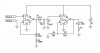
I want to make LEDs sync to music by using the audio from a mp3. I used a TIP31C transistor and connected
the positive of the audio wire to the base
the ground from the battery and the ground of the audio wire to the emitter
the negative of an LED to the collector,
and the positive of the LED to the battery.
The circuit works but the LEDs only respond to the loud parts of the song, and I have my computer speakers set to earsplitting maximum.

The main problem is, I want this to work on an mp3 but even my computer speakers on maximum isn't powerful enough to make the LEDs respond to most of the song. What I want to know is what should I do to fix this problem? Do I need a different transistor? So far, I'm testing this with a 6v battery and 1 led.
 
The transistor you are using is pretty substantial overkill where a smaller transistor like a 2N3904 or 2N2222 would work better to drive a single (or a few) LEDs. However, the main problem is you don't have enough audio signal level to really drive your transistor.

What you are after in a very, very simple form is called a "Color Organ" circuit. If you do a Google of color organ circuit you will get dozens of hits. Take a look at some of the schematics. You will note just about all of them start with a basic form of amplification (transistor or IC) that drives other components that drive the LEDs. That is what you need.

You need a small stage of amplification to drive your transistor that drives the LED.

Ron
 
An op-amp would work best for the amplification because you can control how much the signal gets amplified. I have attached a schematic that is similar to an idea I was messing with a while ago. I have modified it for your purpose so you can change the effect the way you want to.

R2 controls the gain of the audio signal
R3 limits the gain to a maximum of 1,000 (actually 1,001) the gain will be R2 resistance (measured from the output of op-amp 1 to the inverting input) divided by R3 resistance (measured from inverting input to ground)+1

R1 and C1 determine the amount of time that the LED will stay on, to adjust the time constant follow the equation 1.1*R1*C1, the result will be in seconds.

R5 and R6 can be adjusted for any additional gain needed, sometimes a lower gain at op-amp 1, and a higher gain at op-amp 2 will work best depending on the input voltage.

R4 can should be determined by the equation: R = +V - VD2 / ID2 where +V is the battery voltage (which will be the maximum output of the op-amp), VD2 is the forward voltage drop across D2, and ID2 is the current needed by D2.
ex: LED = 1.5V, 10mA with a 12V supply; (12-1.5)/0.01A= 1050Ω (1k is close enough)

B1 can be any voltage between 5V and 30V
 

Attachments

  • LED.JPG
    LED.JPG
    41.6 KB · Views: 258
thanks for the help everyone. Dragontamer, I really appreciate your help, but I feel bad because I'm not exactly sure what everything means because this is my first project >_< and I'm learning this by myself. I'm having trouble learning how to calculate and especially measure things in a circuit.
However, I did try to make an amplifier after receiving responses from this thread. I had the parts to make the cmoy amp with a schematic and directions from tangentsoft. I tried to put it on a breadboard to see if I could connect it properly. There was audio when I connected the mp3 to the amp to my earbuds, but it was strange because the audio coming out from the was weaker than if I were to put my ear buds and listen directly from the mp3. I might have connected it improperly?
I also tried to amplify the signal by using darlington pairs. I had 4 transistors so I connected them together. I was able to light the LED with less volume now from my computer. But if I wanted it to work on a mp3, so I would need a lot more. So I still need to know how to make a circuit using an op amp for the audio.
As of right now, I'm still trying to figure out how to use an op amp. I understand the pinouts, but I don't really understand what each resistor is for when they are connected around the op amp. I don't know how to calculate or figure out where I would need a resistor and calculate what value I would need. What should I do? Is there any helpful resources I can use?
 
The audio circuit posted won't work:
1) Its 741 opamps are 43 years old and are spec'd with only a 30V supply so many don't work when the supply is 10V or less.
2) Its input is not biased at half the supply voltage so it will not work.
3) Its rectifier is not inside the negative feedback loop of the first opamp.
 
Hi,

If you want to still do it with a couple of transistors, here is a quick circuit, that runs off a 9v. battery, it is very simplistic in its design, but works well with a portable CD player, if you want I can take a video of it working, it may work with your MP3, and it may not, depending on it's output impedances, as well as its output voltage, but it's worth a try, if you like.
One of the LED's is used for voltage dropping, while another can be used for your displaying, or you can use both for display.

led music1.jpg
 
thanks for the help everyone. Dragontamer, I really appreciate your help, but I feel bad because I'm not exactly sure what everything means because this is my first project >_< and I'm learning this by myself. I'm having trouble learning how to calculate and especially measure things in a circuit.
However, I did try to make an amplifier after receiving responses from this thread. I had the parts to make the cmoy amp with a schematic and directions from tangentsoft. I tried to put it on a breadboard to see if I could connect it properly. There was audio when I connected the mp3 to the amp to my earbuds, but it was strange because the audio coming out from the was weaker than if I were to put my ear buds and listen directly from the mp3. I might have connected it improperly?
I also tried to amplify the signal by using darlington pairs. I had 4 transistors so I connected them together. I was able to light the LED with less volume now from my computer. But if I wanted it to work on a mp3, so I would need a lot more. So I still need to know how to make a circuit using an op amp for the audio.
As of right now, I'm still trying to figure out how to use an op amp. I understand the pinouts, but I don't really understand what each resistor is for when they are connected around the op amp. I don't know how to calculate or figure out where I would need a resistor and calculate what value I would need. What should I do? Is there any helpful resources I can use?

I think, based on your post, you need to start thinking along the lines of EL101. That means starting with the basics. When you say:

As of right now, I'm still trying to figure out how to use an op amp. I understand the pinouts, but I don't really understand what each resistor is for when they are connected around the op amp. I don't know how to calculate or figure out where I would need a resistor and calculate what value I would need. What should I do? Is there any helpful resources I can use?

Electronics is a funny animal but much like other things where to gain an understanding of what the hell is going on we need to start at the beginning. Something like learning to walk before you run? That or do not jump into the deep end unless you learn to swim or bad things happen.

I guess there are a few ways to learn basic electronics but my best guess would be learning step by step what the components do. An op amp is no more than a collection of components stuffed in a cute little package. The trick is knowing what the components do. Then when looking at an op amp suddenly it begins to make sense. While I don't believe learning an op amp is a great starting point why don't you give this a read. Not great as to electronic theory but interesting history.

Now if you want a quick and dirty way to go about what you are trying to do then consider a toy like this little amplifier. Open it up and gut it (you get points here for modding 101). Place your LED across the speaker leads and remove the speaker. Not quite 100% home brew but it will work. :)

While the old 741 operational amplifier is not quite new and is as AG points out over 40 years old it does work and is fine for experimenting as well as many newer op amps. Hell if we took everything electronic that is old and tossed it out myself, AG, and half this forum would be on a tree lawn awaiting trash pickup. :

Just My Take
Ron
 
I am fairly old, I had a heart attack then rushed to the hospital where they recycled me by fixing two blocked arteries that feed my heart. Now I am fine and am probably better than before even though I was fit and active before. I might be good for another 65 years since I eat better and excercise more now.
 
I am fairly old, I had a heart attack then rushed to the hospital where they recycled me by fixing two blocked arteries that feed my heart. Now I am fine and am probably better than before even though I was fit and active before. I might be good for another 65 years since I eat better and excercise more now.

Well off topic but..............

I was aware of that AG. I figure what was done was they replaced the old 741 with a TL071. :)

Ron
 
I was aware of that AG. I figure what was done was they replaced the old 741 with a TL071. :)
Ron
No, no, no, no, no.
They did not replace me with a much better younger one, they fixed me. Only old teachers (and their students) use a lousy old 741 opamp today.
 
i tried making the cmoy amp on a breadboard again. I only connected one audio channel and it worked better this time. If I only need one channel of audio, can i use both amps for one channel? This is what I'm wondering about, can I connect the output on one of the amps to the other inputs and outputs to get a larger signal? It sounds like I could. Just making sure.

thanks for the help. I think I'll try modding the amplifier from radioshack too.
 

Attachments

  • mini-cmoy-layout-0150.pdf
    158.5 KB · Views: 255
You used low power opamps and made a headphones amplifier not a speaker amplifier.
The opamp has low output current. It should have plenty of output level into earphones.
A power amplifier IC has much more output current and can drive a speaker.


The output of an amplifier "clips" when its output has enough current to swing near the supply voltage and ground. Adding another amplifier will make the same output level but the clipping distortion will be much worse.

The Mini-amplifier from RadioShack has an output of only 0.45W into 8 ohms only when its 9V battery is brand new and has less power when the battery runs down. Its power amplifier IC is the LM386 which costs $.95US at Digikey today.
A cheap little clock radio has more output power.
 
Would something simple like this help? Did i get the orientation of the capacitors correct?
 

Attachments

  • Image0001.JPG
    Image0001.JPG
    160.4 KB · Views: 173
Would something simple like this help? Did i get the orientation of the capacitors correct?
It is the same circuit as before with the same problems except it has two capacitors that do nothing.
1) If the music level is low then the LED does not light.
2) If the music level is high then the stereo, the base-emitter junction of the transistor and the LED all blow up because there are no current-limiting resistors.
 
A capacitor blocks DC but there is no DC. Then the capacitor does nothing.
If the transistor is biased so it is barely turned off then its base would be at about 0.6V which would need an input capacitor (in series with a current-limiting resistor). Then the base-emitter junction would rectify the signal and charge the capacitor so the LED dims if the music keeps playing.
 
Last edited:
A capacitor blocks DC but there is no DC. Then the capacitor does nothing.
If the transistor is biased so it is barely turned off then its base would be at about 0.6V which would need an input capacitor (in series with a current-limiting resistor). Then the base-emitter junction would rectify the signal and charge the capacitor so the LED dims if the music keeps playing.

I took out the capacitor connecting the negative audio signal. How do I calculate the value of the capacitor I need for the positive audio signal. I measured it with 10uf capacitor and i got ~15mV between the (-)audio and the capacitor connected to the (+)audio. I replaced it with a 220uf and I got ~60mV.
 
You do not need a capacitor. When the music signal goes positive more than +0.7V and feeds it to the base of the transistor through a current-limiting resistor then the transistor turns on and lights the LED. The LED must have its current limited with a series resistor.
The datasheet for the TIP31 and most other silicon transistors says that its max allowed emitter-base voltage (reverse voltage) is only 5V so it must be limited with a diode.
 
The problem is the mp3 player I'm using didn't have a strong enough audio signal to trigger the transistor. When I hooked up the circuit like this it started to pulse to the music. I don't think the top capacitor connect to the (+)audio matters because when I removed it, the circuit acted the same way still. It's only when I removed the bottom capacitor connected to the (-)audio that the LED didn't light up at all. Is there a problem with this schematic, should I make any changes? It "looks" like it works when I did it this way. Thanks for your help :D
 

Attachments

  • Image0002.JPG
    Image0002.JPG
    306.2 KB · Views: 143
Last edited:
You seem to already have gotten some pretty good advice in this thread (at least from some people). I know you're a newbie and confused by all this, so I sympathize. Here's my take, for what it's worth:

Forget the TIP31. That's a big honking power transistor that's waaaaaay overkill for what you're trying to do. Look at that circuit posted a ways back that uses a couple 2N3904 transistors (little "jelly-bean" TO-92s). That's all you need.

  • You need a couple stages of amplification to get enough gain to reliably drive your LED(s).
  • There should be a coupling capacitor, like the top one in your drawing, to isolate your color organ from whatever's plugged into it.

I think if you go back through some of the other circuit suggestions that have been given, you'll find one that you can easily breadboard and try out.
 
Status
Not open for further replies.

Latest threads

Back
Top