Continue to Site

Welcome to our site!

Electro Tech is an online community (with over 170,000 members) who enjoy talking about and building electronic circuits, projects and gadgets. To participate you need to register. Registration is free. Click here to register now.

  • Welcome to our site! Electro Tech is an online community (with over 170,000 members) who enjoy talking about and building electronic circuits, projects and gadgets. To participate you need to register. Registration is free. Click here to register now.

LED switch design question

Status
Not open for further replies.

boblob

New Member
Hello all. New here, so please be gentle...

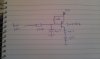
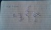
Just wanted to poll opinion on a very simple little LED/2N2222A transistor as switch design I've come up with (see attachment).

The output of a low frequency relaxation oscillator (implemented with a 2n2646 unijunction) is fed in via the 300K resistor to switch the transistor on and off and flash the LED. It is part of an audio circuit and I've found it necessary to add a 4u7 at the base of the transistor to filter the hard edge off the oscillator and stop it from feeding through to the audio (without it you can hear the oscillator ticking away).

I've breadboarded it and it works nicely, but am thinking - do I need some current limiting (like a small resistor from emitter to ground) to protect the transistor from discharge through the base-emitter from the 4u7 cap? Or maybe there's a slightly better way ...
 

Attachments

  • flasher-small.jpg
    flasher-small.jpg
    47.6 KB · Views: 175
Hi bo-blob (or is it bob-lob?) ;)

As a flasher, it is very inefficient, because the current through the 4.7K is always flowing, and is just shunted to ground when the led is off.
A more efficient design would put the transistor switch in series with the resistor/led so that it shuts off that current when the led is off.

Adding a resistor between the 4.7uF and the base of the transistor will lengthen the time the Led is on, but is not really needed to protect the base-emitter junction. The series 330K already takes care of that.
 
Hi Mike - thanks for the reply (it's Bob, BTW).

Yes - it's not an efficient design by any means. I need the LED to pulse at the bottom of the oscillator cycle, which is why I've done it this way. The efficient way with the LED in series with the collector will flash on at the oscillator peaks. I've tried it both ways and it seems to make very little difference to the total current draw of the circuit.

The 330k takes care of limiting current from the oscillator through the base-emitter, but I was wondering about possible discharge from the 4u7. I strongly suspect it's not really an issue, but I'm not much of the "if it don't smoke and it works, play on" school. That's the main issue really.

After a bit more breadboarding I see I could accomplish what I want with a 2N3906 PNP instead (see attached) and have the load in series with the collector (flashing on in oscillator the troughs). Needs an extra 22k to pull the base up and the 2n3906 seems to need more current to the base than the 2n2222a (had to swap the 330k down to 100-150k). The extra draw from the oscillator makes it run noticably faster, which is not so good. Haven't properly checked, but I think the oscillator feedthrough is a bit stronger too - that would be more of a problem. Again, total current draw difference is very small. I guess the 4u7 *really* won't be an issue with this design.

I'd like to go with the 2n2222a solution (for now) as I've already made a PCB. If the cap discharging isn't going to stress it...
 

Attachments

  • 3906-flasher.jpg
    3906-flasher.jpg
    62.1 KB · Views: 167
The attachment for the previous post seems to have messed up and I can't seem to edit the post, so....
 

Attachments

  • 3906-flasher.jpg
    3906-flasher.jpg
    62.1 KB · Views: 165
Your LED current will be < 2mA. Is that enough?
 
Need to know the signal amplitude, freq, duty cycle, rise/fall time at where it says "from Lifo"?
 
"Lifo" = LFO === Low Frequency Oscillator (my handwriting's not the best since the Internet).

OK - amplitude ~2.5V (2 volts at the bottom, 4.5V peak), running at roughly between 1 and 15Hz. I don't have a 'scope, so not sure about duty cycle and rise/fall. It's a unijunction relaxation oscillator like this:

http://www.talkingelectronics.com/projects/DataBook1/DataBook1-22-41_files/image010.gif

The "LFO in" bit in my diagram refers to the output from the base of the unijunction.

As you can see, it's a (sort of) reverse sawtooth produced by charging C through R until the voltage reaches 4.5V, then the unijunction switches on and discharges C very rapidly through RB1 until the emitter reaches 2V, the unijunction switches off and the process starts again. The freq is simply given by f=1/RC. In my application I'm using a 100k pot and a fixed 6k8 in series for R so I can vary the freq.

It's a neat little circuit often found in old electronic organs for producing a tremulant effect (which is why I'm interested in it), amongst other things. Pops up in the Forrest Mims books as well.

Need to know the signal amplitude, freq, duty cycle, rise/fall time at where it says "from Lifo"?
 
Status
Not open for further replies.

Latest threads

New Articles From Microcontroller Tips

Back
Top