Continue to Site

Welcome to our site!

Electro Tech is an online community (with over 170,000 members) who enjoy talking about and building electronic circuits, projects and gadgets. To participate you need to register. Registration is free. Click here to register now.

  • Welcome to our site! Electro Tech is an online community (with over 170,000 members) who enjoy talking about and building electronic circuits, projects and gadgets. To participate you need to register. Registration is free. Click here to register now.

LED Spectrum Analyzer

Status
Not open for further replies.

d3dreaper

New Member
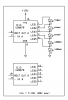
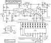
I am currently working on trying to build a LED spectrum analyzer. I hope it to be a 10x10 at the least and I don't want to use micro-controllers or PICs. I have seen the velleman 4300 design BUT the U2067 is not made anymore :confused: . Is there a way that I can multiplex the LM3916? Or should I just use 10 of them and build filters for each channel?
 
I would go for filters on each channel.

I would guess of a solution like this:
For each channel:
1. filter
2. rectify
3. might need to amlify dc value.
4. lead this into a lm3916.

Repeat 10 times.

Interresting problem to try finding another solution so we doesn't have to make up 10 nearly identical circuits.
 
Hmm... that's what i was afraid of... I was hoping maybe i could replace the U2067 with the lm3916. Any Ideas? It seems simple but I haven't the experience yet to know for sure. Also... Are there any circuit design programs and circuit simulators on shareware for a mac out there??
 
Last edited:
If you multiplex a single LM3916 then the 30mA output becomes an average of only 3mA in each LED which is very dim.
If you use millions of transistors then the LEDs will be brighter and only one LM3916 can be used with a switcher from each bandpass filter.

Use 10 LM3916 ICs.
 
Hmmm... The Velleman circuit makes use of transistors at the obsolete IC. Maybe I could ultimatly use the lm3916.... does anyone know where i can get spec sheets for the U2067?? That would help out alot...
 
Maybe I could ultimatly use the lm3916.... does anyone know where i can get spec sheets for the U2067?

You probably want the LM3915 instead, as its 3db steps are closer to the original 2db steps of the U2067B. The LM3916 sports steps for a VU meter (-20, 10, 7, 5, 3, 1, 0, +1, 2, 3db).

Display brightness may be an issue, as AG states, because you're cycling through ten rows, hence 1/10 the brightness. But, the original Velleman kit does the same thing. EDIT: With the values they're using it looks like the LEDs are being driven with about 45-50mA, so it may be okay (4.5-5mA average current). You could drop the 270R resistor a bit to get more brightness, say to 120R/2W. That would give you 10mA average. Also, you'll likely have to dork with the input level at the LM3915 some to get it to work properly. Who knows what the original U2067B did.

In terms of a datasheet, all I could find was this, which basically shows that an LM39xx may get you there. Also, there's a German site that appears to have the datasheet, but it's a pay-per-use or subscription service: data sheet information for U2067B from www.ecadata.de).
 

Attachments

  • U2067B.PNG
    U2067B.PNG
    32.1 KB · Views: 884
Last edited:
The "Peak meter for certain frecuencies"!!! Nice old memories. I never finished the construction, I ran out of money. 10 Lm3915 would be very complex and expensive! Maybe if you buy them directly with the factory they would be cheaper?
 
I bought an LM3915 for $1.00CAN at a local surplus electronic parts store (Sayal). They buy overstocked parts from equipment manufacturers who don't need them anymore.

My Sound Level Indicator project's prototype still works 24/7 and is almost 3 years old. It uses an LM3915 with an automatic gain control to give a range of 50dB. It shows a pin dropped on the floor in the next room and loud music in its room.
 
Last edited:
Anyone know where i can get spec sheets for the U2067??

I found out a bit more about the U2067B by scrounging around through some German web pages, which I drew it up in case it's useful. The thing is a Stereo Level Driver, with each half doing five LEDs and having some sort of precision rectifier.

If the supply voltage is high enough, LEDs can be arranged as drawn, and are sourced with 15mA constant current. As the supply voltage gets less and less, the lower LEDs must start to be wired in parallel. And finally at 7V each output gets its own LED to ground, with a pullup to +Vs, all except the first. The pullup values determine LED current. The chip shorts out each LED as the input voltage falls below the indicated threshold values.

"Aside from the built-in rectifier, the input op amp is used as any other, and the non-inverting input is grounded internally." If the input op amp is not used, the rectifier output pin can be used directly as the input.
 

Attachments

  • U2067B drawing.PNG
    U2067B drawing.PNG
    13 KB · Views: 1,148
Sweet!! Thanks for all the help Ya'll I think I can get it together and figure out any information i need from what ya'll gave me! :D I think I'm goin to make a stereo version of this and have the two stacked one on the other where the lowest amplitudes are nearest each other. I'm goin to paste my schematics as soon as i can get it together and possibly a video of it working.
 
Does Anyone know of any free Circuit Building Programs?
 
Do you mean schematic capture/PCB software? Below link has a free version of which you seek:)
 
Maybe Even some programs that allow for testing as well?
 
A simple 10 band audio spectrum analyzer

About a year ago we had activity in this project. I think some built it. I think there is an error on the power supply pins on an op-amp. If you look back at old posts you will find more information.


look for "audio_spectrum_analyzer.zip"

If the link does not work go to cadsoft - download - projects
 
Hey thanks alot! Well for my final this quarter i decided to build a VU meter instead. I thought i might as well start small and work my way up to learn a bit more before going big. In my schematics for the VU meter though i did have a problem where i had a ground loop and the lm3916's weren't getting any power. I fixed that and it seems to work great! So now since that is done im starting to work on that Spectrum analyzer. And thanks for that link to Cadsoft. Awesome program. I downloaded the spectrum analyzer zip BUT i have not looked at it because i want to draw my circuit first and then compare it. Figure I can learn better that way. :D
 
My Sound Level Indicator project's prototype still works 24/7 and is almost 3 years old. It uses an LM3915 with an automatic gain control to give a range of 50dB. It shows a pin dropped on the floor in the next room and loud music in its room.


Have a schematic for that project you would be willing to share or email to me? I would be very greatful! I am still having trouble with my agc circuit and I would love to see how you went about yours.

Thanks!:D
 
Have a schematic for that project you would be willing to share or email to me?
Here is the schematic for my Sound Level indicator circuit that uses an LM3915 that has a range of 30dB and my circuit adds an additional 20dB of AGC:
 

Attachments

  • Sound Level Indicator schematic rev1.PNG
    Sound Level Indicator schematic rev1.PNG
    66.2 KB · Views: 6,439
Ok Guru, let me give this a shot here.

I see your supply voltage is 9V. The circuit I use has a 12V supply. I am assuming that since the MC33172 can go to 44V that the op amp will be fine, but will that change any of the other component values in the circuit?

You use an electret microphone for your source. I will be using the output of the line level jacks of a car stereo. What design problems do you forsee using this higher input source? Is there a point in this circuit that I could connect my source and maybe lower the input level with a trimpot?

Thanks for your help.
 
Status
Not open for further replies.

Latest threads

Back
Top