Continue to Site

Welcome to our site!

Electro Tech is an online community (with over 170,000 members) who enjoy talking about and building electronic circuits, projects and gadgets. To participate you need to register. Registration is free. Click here to register now.

  • Welcome to our site! Electro Tech is an online community (with over 170,000 members) who enjoy talking about and building electronic circuits, projects and gadgets. To participate you need to register. Registration is free. Click here to register now.

LED resistor

Status
Not open for further replies.

MrDEB

Well-Known Member
This sounds like a dumb question BUT?
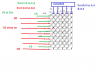
Have a 5x7 LED array https://www.electro-tech-online.com/custompdfs/2011/05/TBC30-12EGWA.pdf
Presently using 220 ohm resistors.
Calculating for 20ma and Vf of 4v I come up with 28 ohm resistors there about?
This seems awfully small value resistor
Using an DMM to measure current, with the 220 ohm resistors in the circuit (one led) I measure 3.2ma (4.5v battery pak)
Something just doesn't seem right?? unless I am just so dumb (frazzled today trying to track down other circuit problems (solved)
Can't be right?
 
You can't calculate a resistor value for an array of this type, it has to be driven from a constant current source because of it's row/column layout makes no one specific resistor value work for all possible state considerations.
 
The max forward voltage is 5.0V so it will not light with a 4.5V supply.
If you use a 7.0V supply then with 5V LEDs a 100 ohm resistor provides 20mA. If the LEDs are 4.4V then the 100 ohm resistor provides 16mA.
 
And if you use static resistors you'll have display flicker.
 
I guess I failed to explain correctly.
Using just one dot in the array, one resistor in series so only one LED is lit.
The Vf as listed in the data sheet at Kingbright, is 4.0
Sorry the link didn't work.
Will repost
 
Your original question: is 28 ohms correct; (4.5 - 4) / 28 = ~18mA for a red led. For a green one it's (4.4 - 4.5) / 28 = 3.6mA

Note that is with a full battery pack - as soon as it drains a little, the current through the LED will plummet (especially with the green one as there's only 0.1V headroom).
 
Where on earth can you buy LEDs that have a "typical" forward voltage? Nowhere.
You get whatever they have and each LED might have a different forward voltage as shown in the spec's.

The maximum forward voltage is 5.0V and maybe all LEDs in the last production run are 5.0V. Then your 4.5V battery (that drops to 3.0V during its life) won't light them or might just barely light them if the battery is brand new.
 
The battery pak consisting of 3 AAA batteries works but I need to up my supply voltage to either a 9v battery or 4 AAA batteries. Would like rechargeable. Even considering coin batteries but ?
First I need to figure out WHY the matrix circuit board does not operate correctly?.
 
First I need to figure out WHY the matrix circuit board does not operate correctly?.
Probably because you battery voltage is too low; try something higher.
 
Where on earth can you buy LEDs that have a "typical" forward voltage? Nowhere.
Are you feeling okay AG? Ever LED I've ever seen that has a datasheet has a 'typical forward voltage' or nominal forward voltage listed. It's the voltage where the diode will start to conduct and depends on the semiconductor type.

Getting back to the OP's question now that he's explained what's going on dougy is perfectly right, the forward voltage isn't high enough, the low resistor value is probably close to competing with the bulk resistance of the diode so there is virtually no regulation going on. LED's should never be run at a fixed voltage, they should always be current regulated, the easiest way to do that is to determine the VF and double it and use a resistor. The closer your power supply gets to the diodes forward drop the less regulation you'll get with resistors and the more brightness variation you'll get as the power supply dies. If you want rechargeable, use a three cell Lithium pack, you could probably get away with two but at a 3.1 volt per cell dropout 6.2 volts is pretty close to the 4V forward you listed, and a fully charged pack will be a bit over 8 volts so you might see some dimming with only 2 cells, then again with three cells you'll just be burning about 1/3rd the power to get the average brightness stable. If you use constant current sources instead of resistors for regulation 2 cells will be fine.
 
Are you feeling okay AG? Ever LED I've ever seen that has a datasheet has a 'typical forward voltage' or nominal forward voltage listed. It's the voltage where the diode will start to conduct and depends on the semiconductor type.
No and no.
An LED has a range of forward voltages because they cannot be made accurately. It does not produce a regulated voltage. If its "typical" voltage is 3.3V when it has a current of 20mA then its voltage is about 3.0V when it begins to conduct. The range of forward voltages listed on its datasheet are probably from 3.0V to 3.6V. You don't know what is the forward voltage of an LED that you buy.
 
Last edited:
Sorry AG, my experiance says otherwise, most LED datasheets I've read there's a min, max and nominal, for simple listings the nominal is given as Vf, but most that I've seen show a Vf that has a testing condition of 20ma, YES there will be variation, but your statement that there is no typical voltage listed for an LED is DEAD WRONG. MrDeb is likely having trouble because he's using the diodes so close to their rated voltage.
 
Here is what my present circuit looks like

I just might have a glitch in my wiring but ?
Going to start from scratch and use a smaller resistors something between 50-120 ohms.
Presently just trying to turn on individual leds (note the matrix is bi-colored) but several problems occur.
Turn on one GREEN led in column (1-7) by going HIGH and making the input to the ULN2803 HIGH thus one LED should turn on.
Not the case. I have say column 3 Green flash at 1 hz But the Red led in same row but column 5(1-5) just stays on, no blink. Change the Green LED to say column 1 and same RED led still stays on while the Green blinks
PLUS row 5 won't come on at all. Either will any LED in colum 6 or 7.
Pretty sure its a connection malady.
 

Attachments

  • paint circuit.png
    paint circuit.png
    50.1 KB · Views: 175
Mr. DEB,
You show only part of the LED driver circuit, the ULN2803A column driver IC that has a typical output saturation voltage loss of about 0.8V if only one LED is lighted and it might be 0.9V if 5 LEDs are lighted. We don't know how much voltage loss there is in the row drivers because we don't know what they are. So it looks like there is no way your LEDs with a maximum forward voltage of 5.0V will work when the supply is only 4.5V which drops to 3.0V.

It is the logic that drives the LED drivers that causes an LED to light or not.
 
The LEDs light up BUT I have a major glitch as only one LED is supposed to be on but I have two LEDs on.
One Green LED is blinking as its supposed to do BUT I have a second red LED that stays on but its not even programed to come on.
Going to start from scratch and maybe find out why?
The matrix is not very well marked but have verifyed which pins are which.
I suspect that when I designed the pcboard I inverted a component or ??
Etching a new board tomorrow and maybe get correct results.
 
Status
Not open for further replies.

Latest threads

New Articles From Microcontroller Tips

Back
Top