Phinehas_Rex
New Member
Hey all! I'm new to the forum and new to electronics. And, I need a little help.
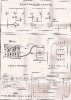
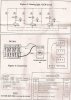
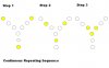
I have an LED flasher circuit kit that I purchased online in the hopes that I could rewire it to do what I want. Alas, I don't have the knowledge! What I want is to design a Y-circuit of 9 LEDs total; 3 in each branch. I want them to chase sequentially to the center in this fashion: outer, middle, inner, and repeat. I didn't want to use a timer because I thought this might be easier and more compact for what I need. Can anyone decipher this scan and give me a clue? Thanks!
I have an LED flasher circuit kit that I purchased online in the hopes that I could rewire it to do what I want. Alas, I don't have the knowledge! What I want is to design a Y-circuit of 9 LEDs total; 3 in each branch. I want them to chase sequentially to the center in this fashion: outer, middle, inner, and repeat. I didn't want to use a timer because I thought this might be easier and more compact for what I need. Can anyone decipher this scan and give me a clue? Thanks!
")