Continue to Site

Welcome to our site!

Electro Tech is an online community (with over 170,000 members) who enjoy talking about and building electronic circuits, projects and gadgets. To participate you need to register. Registration is free. Click here to register now.

  • Welcome to our site! Electro Tech is an online community (with over 170,000 members) who enjoy talking about and building electronic circuits, projects and gadgets. To participate you need to register. Registration is free. Click here to register now.

LED Driver Issues

Status
Not open for further replies.

Smartie

Member
LED Driver Issues [Solved] (Human Error)

Hey guys,

I've been working on a LCD watch project as some of you may know already.
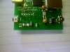
I got the circuit boards from Batch PCB a few days ago and I have assembled one of the boards. this is my very first SMD board and have hand soldered all the components (Solder Paste does a great job :)

However when I program my MCU to turn on the LED Driver, Nothing happens, the charge capacitor does not go over the circuits normal voltage and there is about 1V output on the LEDs...

I'm using a LT3593 LED Driver (Datasheet), it is designed to provide a programmed constant current and boosting the voltage until that current is met (max 20mA though).

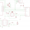
I have tested the output of the MCU to make sure the LED Driver is getting the signal, which it is. I have attached the schematic of the LED Driver.

The LEDs are the backlight to a Nokia 6100 LCD screen which require 6V to run but my battery only supplies 3.7V hence why I'm using a LED Driver to boost the voltage.

The inductor i scavanged from another PCB from my junk box, it reads '100' and I'm sure it's 10uH, (I honestly did try Googling it)

Any idea what's wrong?

Cheers
roman

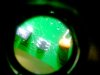
Edit: The LT3593 is the 6pin chip on the bottom, to the left is the inductor, next a Schottky Diode then the two Capacitors C4 and C5
 

Attachments

  • lt3593.png
    lt3593.png
    16.1 KB · Views: 178
  • DSC00332.JPG
    DSC00332.JPG
    336.5 KB · Views: 211
  • DSC00329.JPG
    DSC00329.JPG
    313.6 KB · Views: 178
Last edited:
I've been working on this problem all day today, The Chip itself seems to be fine, I've got it setup in a circuit that was suggested in the datasheet.

I've swapped inductors and that didn't work, i swapped for another IC and that didn't work. When I read the datasheet on selecting a diode, it must be a Schottky diode that has a low capacitance around 10pF. I did not think that this was important until i read up on how switch mode power supplies work and noticed that this LED driver's frequency for switching the inductor is 1MHz. So I've been going through all my junk boards looking for diodes that could possibly be a Schottky diode. Been testing but I'm getting no where.

I'm going to order some Schottky diodes with the recommended values and test it when they get here.
 
You should clean your circuit, I see lots of residue on the macro photo. The flux cleaner to use depends on the type of solder.

Also, I don't see the 1uF supply decoupling cap, where is it ?

What does the scope show ?
 
You should clean your circuit, I see lots of residue on the macro photo. The flux cleaner to use depends on the type of solder.

Also, I don't see the 1uF supply decoupling cap, where is it ?

The 1uF cap is beside the load cap the the right of the inductor.

What does the scope show ?

I don't have a scope sadly, I will have to wait till mid term exams are over before i can take it to school and use the school's oscilloscope.
 
It's going to be difficult to debug this without a scope.

It could be any number of things... do you have a load ? (don't put the LEDs at first, but you can use a resistor of a suitable value for the output current x voltage you expect, for instance, or a dumb zener).

If you didn't use a schottky diode, then that could be the reason. Please post your diode's datasheet.

Also, usually when you do a switcher, layout is very important : for high frequency power, you never use thin long traces, but thick short traces, or better, a mini polygon pour. Component placement is important too : the power parts should be placed tight and close to the IC (just like on the schematic actually) to minimize loop area. The datasheet gives a very good layout, yours is honestly terrible. At 10 kHz switching you can do it with flying wires (a nice noise bomb will result though, but it will work), not so at 1MHz...

If your traces have enough inductance, ringing will occur at every switching event, which can exceed the maximum rating of the switch and simply blow it.

Did you simulate the thing in LTSpice ? It has models for most LT parts.
 
Last edited:
Ok guys I feel like a complete idiot..
I was looking through my box of parts and found a anti static bag with 'LT3593' written on the side, which looked different from the bag i got the chips out of, so i looked for the other anti-static bag to find that they are 'LT3465' so turns out I had the wrong chip installed. They are both LED drivers, except the LT3465 has an internal schottky diode and a different pin layout.

So I soldered in the lt3593 and hey, the LEDs light up.

Thanks for your help

It's going to be difficult to debug this without a scope.

It could be any number of things... do you have a load ? (don't put the LEDs at first, but you can use a resistor of a suitable value for the output current x voltage you expect, for instance, or a dumb zener).

If you didn't use a schottky diode, then that could be the reason. Please post your diode's datasheet.

Also, usually when you do a switcher, layout is very important : for high frequency power, you never use thin long traces, but thick short traces, or better, a mini polygon pour. Component placement is important too : the power parts should be placed tight and close to the IC (just like on the schematic actually) to minimize loop area. The datasheet gives a very good layout, yours is honestly terrible. At 10 kHz switching you can do it with flying wires (a nice noise bomb will result though, but it will work), not so at 1MHz...

If your traces have enough inductance, ringing will occur at every switching event, which can exceed the maximum rating of the switch and simply blow it.

Thanks for your advice, This is my very first proper circuit board and didn't consider everything. I've already found several mistakes of my own on other parts of the board.
When I design the next one, I'll know what to look out for :)

Cheers
Roman
 
Status
Not open for further replies.

New Articles From Microcontroller Tips

Back
Top