Electro Tech is an online community (with over 170,000 members) who enjoy talking about and building electronic circuits, projects and gadgets. To participate you need to register. Registration is free. Click here to register now.
Welcome to our site! Electro Tech is an online community (with over 170,000 members) who enjoy talking about and building electronic circuits, projects and gadgets. To participate you need to register. Registration is free. Click here to register now.
I can't find anything ready made to buy but here is the deal.. it's for a automotive application I need a driver with a 2.8A output and able to handle the voltage from a car.
How simple would this be to build? Where should I start?
that one that selling for $54 is about what I paid for when I had one but from another guy.. long story short the board was much more smaller in person what happened was the board had a short circuit because of the wires on the backside touched and I was out of $40.. I have the project sitting in my car for 2 years and have yet to complete it but I have a ready made 1 A power puck but that's not really giving me the full output I want from the LED's
I can't use a voltage regulator instead of spending another $50?
Yeah those drivers are more made for flashlights. What is the configuration for the leds?, and total Vf at proposed 2.8A.
I built a buck smps for an rv project once with a STM L4692. It worked great, and was in a hard to find DIP package to boot. The power supply switchers seem set up for constant voltage output, not a constant current. I think the internal reference point of the L4692 is too high to make it practical for constant current operation?
ST linear has a parametric table for their led drivers, and all of them are smt of course. If you can find one where a current sense resistor can be added onto for extended power range, you might come up something. If not, try the other suspects like TI, National, Maxim, everyone has them it seems.
In the TI Led Cookbook (Warning 6.6MB pdf) they actually show a h-bridge motor control chip as a high powered 4 channel led driver. It shows it being controlled by a micro, using the a-d to feedback the PWM to the driver. Now that would interesting!
Uhmm the LED's the SSC P7 max current is 2800 mA with a Vf of 3.6 the outup is 700 lm typ and 900 lm max.
i've got a heatsink/fan combo for the driver the fan is loud but heat really should not be that big of an issue unless I'm going to be backing up for 5 min.. but it never hurts to be safe then sorry.. the fan spins at some like 20K or 22K rpms so it does move some air for it's small size.
I was trying to catch whether there is just one led, three in series, two parallel strings?
There was a question like this started here before with a more enlightened discussion of what's involved. I'm stuck with vendor engineering, so here are some more links that might prove interesting. **broken link removed** **broken link removed**
If you don't mind signing up, the National WEBENCH online software has a comprehensive led selection. The list includes SSC's P7, and will make a complete bill of materials for the driver. The **broken link removed**seems like a viable candidate for an auto application.
I think I decided to build the circuit I used the webench software I'm not sure if I can order the parts from the site or I have to source the parts.. the only question I have is what do I mount it on? I have the eagle program but I've not used it for anything yet and not sure where to start at.
Maybe a PC board or free style depending on the circuit. Bigger questoin is whare are you going to put it. In the dash or under the hood, build it into lights?
I think I decided to build the circuit I used the webench software I'm not sure if I can order the parts from the site or I have to source the parts.. the only question I have is what do I mount it on? I have the eagle program but I've not used it for anything yet and not sure where to start at.
You will have to source the parts. Can't help you with Eagle, but willing to help locate the parts. Yesterday I was checking and it seemed that Mouser had quite a few parts spec'd by Webench, might take a couple of sources to get all them.
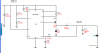
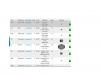
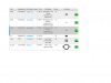
Big help if you could download a screenshot of the schematic, and the bill of materials (Ctrl+PrtSc=>paste in Paint=>crop to fit=>save as .png file=>attach file). I will test below. The LM3409HV is an automotive grade part, with a 10 pin MSOP + exposed pad pattern. Everything is spec'd as smt, so a pcb is probably the way to go.
Maybe a PC board or free style depending on the circuit. Bigger questoin is whare are you going to put it. In the dash or under the hood, build it into lights?
This site uses cookies to help personalise content, tailor your experience and to keep you logged in if you register.
By continuing to use this site, you are consenting to our use of cookies.