Electro Tech is an online community (with over 170,000 members) who enjoy talking about and building electronic circuits, projects and gadgets. To participate you need to register. Registration is free. Click here to register now.
Welcome to our site! Electro Tech is an online community (with over 170,000 members) who enjoy talking about and building electronic circuits, projects and gadgets. To participate you need to register. Registration is free. Click here to register now.
The I/P of the 4026 is Pin 1 you can use a debounced switch in there but disconnect the O/P from the 555 first ( a 3 way switch). There may be a way of switching the 555 with a switch as well but you would need to check out the data sheet. Just do a search on Google etc.
Here a tutorial found on Google.
just replace the 555 clock out put with a press button. someone else may be able to explain how to do a debouce circuit to make it less receptice to false contacts
ok thanks is the clock output pin 3? (the "output" pin) i presumed it was but just making sure
btw, if i replaced the output of the 555 with a push button, would i still need the 555 or could i do it with just a 4026 or would i connect the switch from the output, is this what you mean
Thanks again for all your help
Mike
You do not need the 555 timer the 4026 just needs a connection to the +ve at pin 1 to count. Don't forget to debounce the switch or you will get loads of false counts.
Brett.
hi again, when i connect the battery i get a number 8 (all 7 segments lit), when i press the switch to make it go up, i get only the top left vertical line lit and when the reset is pressed, i get the middle horizontal line and top left vertical line lit any ideas plaese?
ok, thanks for the quick reply, i have done that but now when battery is connected, fig. 8 shows, when reset is pressed, nothing happens and when the count switch is pressed, the vertical line lights up (same as before)
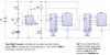
I think this will work. The 4026 has a Schmitt trigger clock input, so you just need RC filtering for debouncing.
Notice that the CE input to the 4026 needs to be tied to GND (the negative side of the battery), and I have added a 0.1uF cap across the battery for decoupling.
This site uses cookies to help personalise content, tailor your experience and to keep you logged in if you register.
By continuing to use this site, you are consenting to our use of cookies.

 is the clock output pin 3? (the "output" pin) i presumed it was but just making sure