Continue to Site

Welcome to our site!

Electro Tech is an online community (with over 170,000 members) who enjoy talking about and building electronic circuits, projects and gadgets. To participate you need to register. Registration is free. Click here to register now.

  • Welcome to our site! Electro Tech is an online community (with over 170,000 members) who enjoy talking about and building electronic circuits, projects and gadgets. To participate you need to register. Registration is free. Click here to register now.

led circuit design help

Status
Not open for further replies.

jagmanjoe

New Member
I am new to this site and very new to wiring leds. I have a new home I built and in anticipation of wiring for low voltage led lighting, put a fair amount of cat5e in the walls.

My first large endeavor is to wire undercounter lights and I plan to make my own lighting using 2 luxeon style stars for under each cabinet -- 5 cabinets total. The stars I have are 3 watt, 650 milliamp and have a forward voltage of 3.6 to 4 volts.

If possible, I want to have a rocker style on off switch for each cabinet and a master dimming control using a pwm kit.

To supply the led systems I have a small bank of 12 volt batteries that will be recharged through a solar panel. I also plan to place a voltage regulator prior to the supply of the cat5e in order to limit the maximum voltage.

I plugged info into a resistor calculator which suggested the resistor value for each of the arrays should be between 6.8 and 8.2 ohms but does not suggest a wattage.

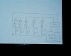
I have attached a rough wiring drawing -- please excuse my lack of proper symbols on the drawing.

I would appreciate any thoughts on my rough wiring drawing as well as suggestions for a pwm dimming kit/method as well as suggested wattage for the array resistors. Also, if I am way off base on this and it can not be done with one dimmer, please let me know.

Many thanks,

Joe H
 

Attachments

  • ledwir1.jpg
    ledwir1.jpg
    29 KB · Views: 223
For resistor power rating, using the lower LED voltage drop of 3.6V to get an 8.4V drop across the resistor yields dissipated power at (4.8*4.8)/8.2 - or 2.8W. Always use a resistor that is rated at 2x the power being dissipated - which would be a minimum of a 6W resistor. Looks to me like this is going to be a fairly warm system that may require some heatsinking.

Another thing to think about is the battery bank. I don't know the capacity of the bank, but if the LEDs are left on long enough, you will see a dimming of the light intensity without any type of PWM circuit involved due to the drop in battery voltage. You may want to look into a constant current circuit and also some type of shut off feature that kills power to the LEDs of the battery bank voltage gets too low.
 
Why not use a switched mode power supply rather than all those resistors?
 
Always use a resistor that is rated at 2x the power being dissipated - which would be a minimum of a 6W resistor.

Why do you say that?

There's no need to derate unless there ambient temperature is higher than the one given for the power rating on the datasheet. Sometimes it's even safe to over rate if it's cold or the duty cycle is low. For example a 3W resistor might be able to take 10W pulses at 30% duty cycle or continiously dissipate 6W at an ambient temperature of -5°C.

Building an SMPS isn't hard, if you limit the duty cycle of the PWM to 60% then you could both safely and efficienctly drive the LEDs by adding an inductor and shotky diode.
 

Attachments

  • LED SMPs.GIF
    LED SMPs.GIF
    2.7 KB · Views: 187
Last edited:
Thanks for the switched mode power supply suggestion. Are you speaking about a Buck Puck? And, would I place the dimmer before or after that? Also, since I am speaking of controlling 5 separate arrays and have cat 5e in the walls, I guess I could then use one leg of the cat5e for each of the arrays with the 6th wire for the common ground. Does that make sense as an option. Finally, I do plan to heatsink the components to keep everything from getting too warm.

Joe H
 
Last edited:
Yes, you could use a Buck Puck which is a kind of ready built switched mode power supply.

The circuit I have attached can be used after the PWM dimmer, indeed it won't work without a PWM dimmer. You need to be careful with the duty cycle of the PWM dimmer because it will blow up the LEDs if it's set higher than about 60%.
 
Why do you say that?

There's no need to derate unless there ambient temperature is higher than the one given for the power rating on the datasheet. Sometimes it's even safe to over rate if it's cold or the duty cycle is low. For example a 3W resistor might be able to take 10W pulses at 30% duty cycle or continiously dissipate 6W at an ambient temperature of -5°C.

Yeah - I can derate all I want in fantasy land, too. But, I highly doubt that it would be -5°C inside this guys house. If he were to use resistors with the LEDs and PWM the LEDs, having a 3W resistor would be fine at 50% duty cycle and below. If that is the brightest he would have it, then fine - but if he wants to take it to full brightness then the duty cycle would be 100% and those resistors are going to cook.

One more thing - If a PWM dimmer is going to be used, it should be placed close to the LEDs - unless the wire is shielded. PWMing across open wire is just going to radiate.
 
If he were to use resistors with the LEDs and PWM the LEDs, having a 3W resistor would be fine at 50% duty cycle and below. If that is the brightest he would have it, then fine - but if he wants to take it to full brightness then the duty cycle would be 100% and those resistors are going to cook.
No they're not going to cook, if they're rated for 3W, they'll be able to safely dissipate 3W so using 6W resistors would be a waste of money.

The only time you can justifiy using a higher powered resistor is if it's operating at a high temperature.

For example, look the datasheet for some 0.5W resistors, at temperatures up to 70°C they can safey dissipate 0.5W. You only have to derate if the ambient temperature is higher than 70°C.

**broken link removed**

I couldn't find the derating curve for any 3W resistors but I imagine the temperature in his house is nowhere 70°C so there's no point in using larger resistors than 3W.
 

Attachments

  • Resistor derating.GIF
    Resistor derating.GIF
    14 KB · Views: 296
No they're not going to cook, if they're rated for 3W, they'll be able to safely dissipate 3W so using 6W resistors would be a waste of money.

And it provides a built-in toaster! :D

3W is the absolute maximum they will dissipate, they will be hot enough to cause severe burns - far, far, better to use more conservately rated components.
 
3W is the absolute maximum they will dissipate, they will be hot enough to cause severe burns -
What's your point?

So do incandescent lamps.

far, far, better to use more conservately rated components.
If they're in contact with something highly flammable, easilly damaged or where they could burn someone then I'd agree but if they're just soldered to a PCB, away from temperature sensitive components, in a piece of equipment then I don't see the point.

The temperature rise vs power dissipation can be found on the datasheet, if it causes a problem then by all means, use higher rated components
 
If they're in contact with something highly flammable, easilly damaged or where they could burn someone then I'd agree but if they're just soldered to a PCB, away from temperature sensitive components, in a piece of equipment then I don't see the point.

Reliability - running a 3W resistor at 3W isn't going to be reliable, it's also going to cook the soldered joints holding it in place and damage the PCB.

Good design doesn't stress components to that degree.
 
The point is that you shouldn't run any component at its maximum rating - there is no factor of safety. Do what you want with stuff that you build and use yourself but I would caution against advising others to do so.
 
I agree you shouldn't push components to their maximum ratings and I'm not suggesting that you should.

You're not running the resistor at it's maximum rating because power dissipation is just 2.88W, not 3W and the ambient temperature is way below 70°C.

If you were planning to use it to dissipate nearly 3W in an environment where the temperature is approaching 70°C then I'd agree but you're not.

Solder melts at a temperature of about 200°C and won't be melted by a 120°C resistor.
 
Last edited:
You're not running the resistor at it's maximum rating because power dissipation is just 2.88W, not 3W and the ambient temperature is way below 70°C.
OK - Let's not quibble about 0.12W. For all intents and purposes, 2.88W is 3W - the difference is only 4%. And I suppose that you would expect this resistor to be exposed to the open air? I would think not - unless you're suggesting that a circuit that is used to control lighting in a home environment be fully accessible 100% of the time. I would play it safe and assume that there will be some type of enclosure involved here so that the resistor itself will be creating the ambient temperature, which would be well over 70C.
Solder melts at a temperature of about 200°C and won't be melted by a 120°C resistor.
A resistor running continuously at 120C would have a very high probability of damaging the FR4 board material.
 
Solder melts at a temperature of about 200°C and won't be melted by a 120°C resistor.

I didn't say it 'melts it' - it 'destroys it' - it's common where resistors are under specified like you're suggesting, the soldered joint, the PCB, and the wire of the component are all ruined making repairs difficult.

I don't know what happens chemically, but the copper of the board, and the wire itself become impossible to solder to, and the old solder becomes crystalline.

Just do the job properly, apply sensible design considerations, and build a circuit that's made to last.
 
I derate stuff because I get too many questions when things run "hot" (>55c) and it's cheaper (mostly the value of my time) to just make it run a little bit cooler.
 
OutToLunch;342035I said:
would play it safe and assume that there will be some type of enclosure involved here so that the resistor itself will be creating the ambient temperature, which would be well over 70C.
  • It doesn't matter whether you use a 3W resistor or a 6W resistor, providing the power actually dissipated is the same, the temperature rise inside the case will be the same.
  • The case ambient temperature shouldn't exceed 70°C as it could burn the user. If you think it's going to get that hot then add ventilation holes.
A resistor running continuously at 120C would have a very high probability of damaging the FR4 board material.
I don't know about that. It depends on the board material, cheap paper composite board might be damaged but I can't see more expensive fibreglass board being damaged - always read the datasheet.

Another thing you can do is leave a gap between the PCB and resistor so it doesn't heat the board too much.

I didn't say it 'melts it' - it 'destroys it' - it's common where resistors are under specified like you're suggesting, the soldered joint, the PCB, and the wire of the component are all ruined making repairs difficult.

I don't know what happens chemically, but the copper of the board, and the wire itself become impossible to solder to, and the old solder becomes crystalline.

Just do the job properly, apply sensible design considerations, and build a circuit that's made to last.

As above, leaving a gap between the PCB and the resistor will help to minimise this effect as the temperature at the soldered junction will be much lower.
 
Last edited:
As above, leaving a gap between the PCB and the resistor will help to minimise this effect as the temperature at the soldered junction will be much lower.

I'm already talking about resistors mounted well off the board - it's a bad idea running resistors near their limits - there's no justification for it.
 
Status
Not open for further replies.

Latest threads

New Articles From Microcontroller Tips

Back
Top