Continue to Site

Welcome to our site!

Electro Tech is an online community (with over 170,000 members) who enjoy talking about and building electronic circuits, projects and gadgets. To participate you need to register. Registration is free. Click here to register now.

  • Welcome to our site! Electro Tech is an online community (with over 170,000 members) who enjoy talking about and building electronic circuits, projects and gadgets. To participate you need to register. Registration is free. Click here to register now.

led bargrpah fuel gauge

Status
Not open for further replies.

gizmo13

New Member
Hey all,

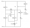
I found these schematics/diagrams in another thread (a year old or so) and wanted to know how do I go about finding out what resistors to use for a 0 ohm/ 90 ohm fuel sender.
This is for an autombile not a motorcyle like the diagrams were inteded and it is using 12v
not 8v like the user wanted.
The other schematic is for a warning indicator that will flash as the fuel level gets near empty.
I need my electronic "wizards" assistance on this.
Thanks.
 

Attachments

  • 1563-16149d1198386129-help-me-build-gas-gauge-fuel-2.gif
    1563-16149d1198386129-help-me-build-gas-gauge-fuel-2.gif
    12.2 KB · Views: 3,569
  • GasGauge1.gif
    GasGauge1.gif
    16.9 KB · Views: 1,854
  • Fuel%20gauge%20flash.PNG
    Fuel%20gauge%20flash.PNG
    1.2 KB · Views: 1,262
Regarding the first schematic. It uses a 12V supply as you requested.

The sender is one leg of a voltage divider with the 150R and 250R trimmer on the other. I expect that one installs the unit and adjusts the trimmer to just read full with a full tank.

There may be enough adjustment/range to work as is. If not reduce the 150R to 100R and give it a try.
 
Last edited:
That's great, thanks.
I want to expand the reading to 15 led's.
Can I do that by adding an additional lm3914 and still be able to use the trimmer for adjustments
accordingly????
 
Check the datasheet for the LM3914; it shows an example of how to cascade two LM3914s.
 
Thanks for the replies.
As I am in the process of drawing up a schematic to have you guys "check" my work before I breadboard and test it, I have a question:
Since I am using 15 led's and not 20, how does it work to not have the other pin-out connected?
I mean can I leave the others not connected to anything or do I have to have one of the others
grounded out or what?
 
You just leave the unused outputs of the LM3914 unconnected.
 
Have you got the cascading right? Looks to me as though the left chip will sense greater voltages than the right chip.
 
I am still learning (slowly, lol).
I don't know what cascading is. Also, could you explaing about the left chip sensing greater
voltages?
I have other schematics that I "borrowed" from to get this.
I wanted to make sure I did it correctly to have to lm3914's connected to have 15 led's.
I used the values from the other schematics.
I really have no idea how to design these. I can build from them with no problem.
That's why I am on this forum, to learn how to do it myself.
I appreciate all the help, by the way.
 
Last edited:
I don't know what cascading is
Have a good read of the 3914 datasheet. It explains cascading. BTW you don't need resistors in series with the LEDs (the chip provides controlled current for the LEDs).
 
read the datasheet and looked at the diagrams and understood nothing about cascading.
Sorry to be a noob but what does it mean?
 
It means connecting two or more ICs in a chain so that input voltages from, say, 0V to 2V are handled by the first IC and voltages from, say, 2V to 4V are handled by the second IC, and so on.
 
No. Why do you think it would be?
 
Newbie remember. Don't know much about designing these.
So should the voltages be evenly distributed through both ic's?
If so, how do I do that?
 
Status
Not open for further replies.

Latest threads

New Articles From Microcontroller Tips

Back
Top