Continue to Site

Welcome to our site!

Electro Tech is an online community (with over 170,000 members) who enjoy talking about and building electronic circuits, projects and gadgets. To participate you need to register. Registration is free. Click here to register now.

  • Welcome to our site! Electro Tech is an online community (with over 170,000 members) who enjoy talking about and building electronic circuits, projects and gadgets. To participate you need to register. Registration is free. Click here to register now.

LDR question

Status
Not open for further replies.

1-3-2-4

Member
I'm building a nightlight that uses two blue cree LED's I want it to turn on and off at dawn/dusk..

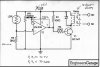
Anyways i was looking on my scope and I'm using a LM339 and on pin 6 where the LDR is connected with light on the LDR I'm seeing 12 V and in a dark room it's about 1.2V or so..


Does that sound right? It's not giving me anything on the output.
 
do you have a ref voltage on pin 5? your output would be on pin 1...check out this link **broken link removed** this might give you a bit of help.
 
I should of pointed out I'm not using all the pins just only using 1,3,7,6 & 12 The quad was just here locally.

I'm using a IRF510 as a switch

I have voltage on the VR1 and adjusting it works and all.. however I'm having issues getting power to the mosfet I see no change on the output of pin 1.. Does pin 1 need voltage?
 

Attachments

  • thumb.jpg
    thumb.jpg
    53.6 KB · Views: 150
Where are the unused inputs going? Are they configured like the drawing you posted? I assume you have a 10K pull up resistor on your pin 1 as shown? Also, what is the gate resistor value you are using? You would not want 20K as shown for R2 in the drawing since you mention an IRF 510 MOSFET.

Ron.
 
If the unused inputs are per the drawing and the MOSFET is in correctly it should work. You could disconnect the MOSFET gate and see if you get the voltage swing at your output on pin 1.

Ron
 
Sounds like the comparator is duff or is not correctly wired.
 
can't be since I have voltage to it.. The wire from the LDR to pin 6 goes before the resistor, no? The other end goes to GND

The VR1 one end goes to the LDR and the other end to Pin 7 of the LM339 and the other leg to GND

just that alone I should be seeing something on Pin 1..

However pin 1 perhaps The R1 is a pulldown right? Is it just an output? because I'm trying to figure out how the R1 would effect pin 1 at all.
 
R1 is a Pull Up and is required. The comparator has open collector outputs. Scroll down this page and note the photocell circuits. R1 is essential as again the chip has an open collector output. I also asked earlier where the unused inputs are going? Also read up on the examples in the link.

Ron
 
Last edited:
R1 is a Pull Up and is required. The comparator has open collector outputs. Scroll down this page and note the photocell circuits. R1 is essential as again the chip has an open collector output. I also asked earlier where the unused inputs are going? Also read up on the examples in the link.

Ron
Yeah I saw that message early this morning before I left for work, the only reason why I did not tie those unused pins to anything yet was at the time I did not think it was needed just for a quick check.

Have you considered a simpler circuit like this?

(One on left is "off". On right is "on". Note current usage levels).


View attachment 60288 View attachment 60289

I'm using it to drive two Cree LED's at 1 A would that handle it?

I rather just stay with what I have here since it's already on the board and all.
 
Probably not. The 2N2222 is only good for about 500mw.


But the same circuit with the LEDs replaced with the relay, R1 changed to 100 ohms and and R2 changed to 1K ohms, will work. This would allow you to keep most of what you already done. It would just get rid of some of the complication.

I do understand about changing designs in mid-stream: sometimes its worth it, sometimes not.
 
Hmm perhaps the wire for Pin 6 should go AFTER the resistor? maybe that's why I'm getting the same voltages on pins 6 & 7 all they do is mirror one another when that should be triggering the output.
 
From the beginning. Swap the positions of R3 and the LDR. Using an ohmmeter measure the Light and Dark resistance of your LDR out of circuit. The value of R3 should be about three times the value of the LDR with normal ambient light striking it. That sets up what amounts to a voltage divider consisting of the LDR and R3 in your schematic. The junction of the LDR and R3 goes to pin 6 (the - inverting input of the LM339 comparator). The top of R3 goes to your 12 volts and the bottom of R3 goes to ground. If you measure from the junction of them to ground you should see a varying voltage going to pin 6. VR1 can be a 100K pot or a 10K pot, it only is used to provide a reference voltage to pin 7 (the + non inverting input) of the comparator. If you adjust VR1 across its range you should see a varying voltage off the wiper to pin 7. As drawn the relay should be on when the LDR is dark.

R1 the 10K resistor is a pull up and is required for the open collector output of the comparator. R2 should be lower than the 20K shown, try about 1K for the transistor base resistor. The LM339 is a quad comparator and as shown in the drawing the unused inputs need to go somewhere. Tie them to your 12 volts and ground as shown. That is necessary all the time. The 220K resistor between pin 1 and pin 7 is there for hysteresis.

So reverse the positions of the LDR and R3 and see what you get.

Ron
 
Good news.. turns out the way i had the LDR connected was right but it's true about the open collector stuff :-| I feel so stupid now wasting all that time.. but then again you have to learn one way or another..

One other thing is this relay I have I swear I checked it before I put it in however I'm not too used of mini relays I know where the coil is but when I put the relay on I connected the solder to both terminals and the ground to the single point
 

Attachments

  • relay23.jpg
    relay23.jpg
    13.9 KB · Views: 112
i've gotten into the habit of visually checking all the solder joints after cleaning them, and if they're questionable, i use a magnifing glass and or a dvm on them. it saves some headachs later.
 
OK and glad it is working.

Ron
 
Status
Not open for further replies.

New Articles From Microcontroller Tips

Back
Top