Continue to Site

Welcome to our site!

Electro Tech is an online community (with over 170,000 members) who enjoy talking about and building electronic circuits, projects and gadgets. To participate you need to register. Registration is free. Click here to register now.

  • Welcome to our site! Electro Tech is an online community (with over 170,000 members) who enjoy talking about and building electronic circuits, projects and gadgets. To participate you need to register. Registration is free. Click here to register now.

LDR Feedback Control

Status
Not open for further replies.

skyryan

New Member
Hey guys,

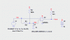
About a month ago, I asked for help on a way to remove the sun's effects on a photoresistor and using a photocell circuit comparator was suggested. I have since built and incorporated the comparator into the system and has, in essence, worked great, but I do need a bit more help on it.

The problem y'see is that although I could tweak the circuit to make it just slightly take out the sun's effects on the photoresistor (so that it may only turn on when I use the laser), the intensity of the sun kept changing, thus altering my set point. Whereas most cases only need a single finite point that will be on if the intensity of the sun is strong enough and off if it isn't, ie a garden light between no light at all and some of the sun's light, it would seem that I need to constantly change the resistance in order to compensate the changing sun intensity.

So now what I need to do is somehow connect this to a device of some sort that will be able to constantly take into account the sun's intensity and change the photocell circuit's comparator to the point where it has just turned off the system and a simple laser will be able to turn it back on.

I know that this has somewhat gone from a pretty simple photocell circuit to one that is more elaborate but I was wondering if you could please point me in the right direction to go about doing my project.

I look forward to hearing your suggestions.
Thanks for your time and help,
Ryan
 
Last edited:
If I understand you correctly that you need a remote switch you operate by shining a laser at the sensor, Then David Cook's Robotroom has a circuit idea that is simple to the point of genius;
https://www.robotroom.com/Laser-Detector-Remote-Control.html

It uses TWO LDR sensors (that self-balance under any room lighting) and switches the output when the laser shines on ONE sensor. I think it will do everything you need and only uses one little 8pin comparator IC.
 
Alternatively, you could ac couple the output from the LDR into the comparator (put a large cap between the (LDR + bias resistor) and the comparator input. This would act as a high pass filter (to remove the slowly changing sunlight) but pass through the sharp rise in brightness when you shine the laser on it. You would have to lower the trip threshold on the comparator, as now the LDR + resistor will give 0 output when there is no *change* in brightness and you will probably need a large coupling cap, but it should work. Also, put a large value resistor (100k?) connecting the comparator side of your capacitor to ground - thus your comparator input wont be floating about. One more point - make sure the LDR is on the top of the resistor network, so when the bright laser comes along, the ouptut voltage from LDR + resistor is a positive spike not a negative one - in case you are using a single supply comparator. I see no reason why this should not work and it will be a simple mod to your existing circuit and requires no extra LDR
 
Alternatively, you could ac couple the output from the LDR into the comparator (put a large cap between the (LDR + bias resistor) and the comparator input....
That would work unless he needs to detect a response to the laser signal for a long period of time. In that case he would need a DC coupled circuit, such as the two LDR design.
 
hi,
This type of circuit, some times called a 'slicer' can take care of ambient light changes.
This image is just an example.
 

Attachments

  • AAesp02.gif
    AAesp02.gif
    11.5 KB · Views: 193
Thanks for the numerous responses guys. It is very much appreciated.

I had a quick look at the workings from the first responses and that is in essences what I need for my project. However whereas in his project he wants the LED to stay on even after he takes the laser off the on-LDR, I only want the LED to be on if the laser is pointed at the on-LDR. Does that mean I just have to take the memory part out of the equation, thus making it a comparator with 2 LDRs? Or is there more to it than that (sorry I haven't had a chance to have an in-depth look yet, but I'll be doing that within the next few days and get back to you guys).

Thank you.

EDIT: Actually, is what I want basically the first diagram in his page that just handles laser detection?
 
Last edited:
Beautiful! You are an absolute champ Mr RB. I'm going to start buying the components tomorrow and work on it over the weekend. I'll post back with how I go.

Thanks mate and also to everybody who also put in their inputs. Much appreciated!
 
Ok, so I finally got around to making my first prototype and the results were mixed. As a note, I couldn't find the TI TLV3072 that he was adamant on using and so instead opted to try using a basic LM393 comparator. Seems to have done the job. Now the results:

Even though I follow his circuit to the T, my circuit did not give me the same results as his. For a starter, my LED is on all the time rather than off, ie it turns off when the laser is pointed at the LDR rather than the other way around. I'm pretty sure this is a simple fix but I'm struggling to see where I made the mistake since I followed his circuit.

Secondly, my circuit acts in the same way as his in the sense that ambient light no longer affects my circuit. However, while both of his LDR acts a switch, only one of mine does. Now this is actually quite fortunate for me because it means that one of my LDR acts as a comparator for ambient light but at the same time it doesn't.

Wait what?

Yes it puzzled me too. While his LDRs always had to be in the same environment, my LDRs does not. This is fortunate for me because to be honest, I only wanted one LDR showing and the other one hidden.

Now here is the hard part, is any of you able to explain to me how my second conundrum is possible? Because I've thought it through and it just doesn't quite make sense to me. I've tried removing the non-acting LDR (replacing it with just a wire) and without it, my circuit no longer takes out the effects of ambient light, meaning that it is having an effect, albeit a different one. If any of you guys can explain it to me, it would be much appreciated.

Thanks guys!
 
Last edited:
Status
Not open for further replies.

Latest threads

New Articles From Microcontroller Tips

Back
Top