Continue to Site

Welcome to our site!

Electro Tech is an online community (with over 170,000 members) who enjoy talking about and building electronic circuits, projects and gadgets. To participate you need to register. Registration is free. Click here to register now.

  • Welcome to our site! Electro Tech is an online community (with over 170,000 members) who enjoy talking about and building electronic circuits, projects and gadgets. To participate you need to register. Registration is free. Click here to register now.

LDR connection-help-

Status
Not open for further replies.

zeeba

New Member
Hi

Im sensing the lights with 2 LDRs and using them as an ADC inputs to PIC 16F876A
the code should see the difference and gives an order to DC motor to move

right now my code is fine the only problem I have now that the LDRs read different readings but there is no output from the pic.

without the ldrs, when I put different voltages instead of them I get an outout from the pic

that means there is a problem in the LDR circuit right? how can I solve it?

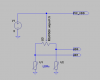
Im connecting them same as this picture

**broken link removed**
 
Last edited:
And what voltage might the arrow be? Hopefully 5Vdc

Put the scope on it and see what is going on. You may not have any voltage at all on the A0 -A1 points depending of the LDR you are using and the ambient light.
 
You want your pots to be about 3X the value of your LDRs when light is striking them. Measure your voltage at A0 & A1 and see what the PIC is getting.

Ron
 
And what voltage might the arrow be? Hopefully 5Vdc

Put the scope on it and see what is going on. You may not have any voltage at all on the A0 -A1 points depending of the LDR you are using and the ambient light.

yes it is 5V dc
Im having A0=0.18V and 0.1mA
A1=0.11V and 0.1mA

what do you suggest??
 
Have you measured the light / dark resistance of your LDRs? You have a LDR in series with a pot (0 to 10K) so you have little more than a voltage divider correct? The pot is known so I would measure the light & dark LDR resistances.

Ron
 
Have you measured the light / dark resistance of your LDRs? You have a LDR in series with a pot (0 to 10K) so you have little more than a voltage divider correct? The pot is known so I would measure the light & dark LDR resistances.

Ron

Im not sure if I got you right
what I did is I measured LDRs resistans using ohm meter
LDR1=5k ohm and LDR2=11.3Kohm and Im Connecting variable resisters both=10k
the LDRs are connected as shown in my first post
 
What I initially posted was:

You want your pots to be about 3X the value of your LDRs when light is striking them. Measure your voltage at A0 & A1 and see what the PIC is getting.

Meaning measure each LDR out of circuit and note the Light and Dark resistance. The LDR covered is Dark and with plenty of light striking it is Light resistance. If both LDRs are the same type their light & dark resistances should be about the same.

OK, if LDR1 for example is 5K with light striking it and your pot (10K pot) is set about midrange (5K) and V is 5 Volts you should see about 2.5 volts Vout. You would have basically a resistor voltage divider of 5K and 5K in series. This assumes open circuit (not connected to your PIC chip). You are seeing pretty low voltages which would lead me to believe something is loading your Vout. Disconnect your Vout from the PIC and measure the voltages.

Ron
 
your o/p voltages seem too low.Measure LDR's light and dark resistance and then set your POT resistance accordingly.So that you'll get sufficient analogue voltages.
 
well, I measured LDRs light resistans using ohm meter
LDR1=5k ohm and LDR2=11.3Kohm
for now Im Connecting variable resisters both=10k
what I understood from you now is that the 10k is fine for LDR=5k but the other LDR=11.3k should be connected to bigger value
did I got you right???
 
What I suggested was to disconnect the LDRs and their series resistors from your PIC and measure your Vout. The Vout voltages you posted earlier are way too low. Something about all of this just isn't right. I also asked if these are supposed to be the same make and model of LDR? If you have a 5 K resistance LDR with light and set the pot for about 5 K you should see a Vout of about 2.5 volts.

Ron

actually the ohm values of the LDRs in the previous post were taken without the pic.
A0 and A1 without the LDR circuit =5v
 
Then something is very wrong. You have an LDR with a light resistance of about 5 K Ohm so you have what amounts to a 5 K resistor. If you set your pot to about 5 K Ohm you have two 5 K ohm resistors in series with 5 volts applied. This is a voltage divider ans if we assume the 5 volts is 5 volts constant and you measure in the middle between the LDR and the pot you should have about 2.5 volts. That is all there is to it. It doesn't get any simpler. I don't know what to tell you or suggest at this point. Maybe someone else has a thought?

Ron
 
Here is how I would do it. Makes it much easier to balance initially.
 

Attachments

  • DF125.png
    DF125.png
    11.7 KB · Views: 190
Status
Not open for further replies.

Latest threads

Back
Top