Continue to Site

Welcome to our site!

Electro Tech is an online community (with over 170,000 members) who enjoy talking about and building electronic circuits, projects and gadgets. To participate you need to register. Registration is free. Click here to register now.

  • Welcome to our site! Electro Tech is an online community (with over 170,000 members) who enjoy talking about and building electronic circuits, projects and gadgets. To participate you need to register. Registration is free. Click here to register now.

LCR meter. (And prototyping)

Status
Not open for further replies.

yngndrw

New Member
Hi,

I have recently found this:
https://electronics-diy.com/lc_meter.php
Which got me thinking, how would I go about building an auto-ranging LCR meter ?

I was thinking something along the lines of having a set of Reed Relays which would select between the L, C (Both like in the link) and R (A potential divider) sections and also the different ranges. The problem is auto-selecting between which mode.

Any ideas ? Is it worth just buying something like this instead:
https://cpc.farnell.com/jsp/search/productdetail.jsp?sku=IN04098

---

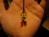
Also on a different subject - I'm looking for ideas on ways to prototype. I usually use a bread board and then strip board. Attached is a recent project which was done on a strip board which has come out very small and quite cute, but there are probably better methods.

I currently have a 20x4 LCD plugged into my breadboard with a pin header but I'm worried that when I remove it - The holes won't grip wires very well.

In another thread, it was suggested to make PCB's of common circuits and connect them together with wires, saving on re-building the common circuits and also saving breadboard space, but what other methods are there ?

Thanks,
-Andrew.

PS: Yes I have Googled.

---

Edit: Oh, before I forget - What are the usual wattages for SMD resistors ? In particular 0805 and 1206 ?

---

Edit2: Okay I know I'm annoying with having 4 questions in a thread, but it saves cluttering the Forum:
Has anybody got one of these:
**broken link removed**
Are there any other sizes of tip that fit it ? Maybe from a different iron that fits anyway ? Suggestions for a decent temp controlled soldering iron with LCD to show temp and different tips ?

Do 24V DC Therm-controlled soldering iron's use the same connectors ?
Would this fit my base station do you think:
https://cpc.farnell.com/jsp/Tools,+Storage+&+Handling/Soldering+Stations+&+Tools/WELLER/WMP+++WDH+20/displayProduct.jsp?sku=SD01199
It's just that the Weller systems seem good, but are very expensive. :eek: I would love that iron even if I had to use my own base.

Thanks.
 

Attachments

  • DSC00045.JPG
    DSC00045.JPG
    312.4 KB · Views: 705
Last edited:
yngndrw said:
Hi,

I have recently found this:
https://electronics-diy.com/lc_meter.php
Which got me thinking, how would I go about building an auto-ranging LCR meter ?

I was thinking something along the lines of having a set of Reed Relays which would select between the L, C (Both like in the link) and R (A potential divider) sections and also the different ranges. The problem is auto-selecting between which mode.

Any ideas ? Is it worth just buying something like this instead:
https://cpc.farnell.com/jsp/search/productdetail.jsp?sku=IN04098

There are various example projects about, Elektor published one the other year - but the Peak meters are really pretty good, reasonably priced, and VERY small - plus they are PIC based (and made not far from me!).
 
Just looked at Elektor and the only projects I can find are separate. I'm thinking that it's probably much better to just buy one, more features and probably less £ than hours spent designing and building.

They look quite big in the picture but I'll take your word for it. Anything I build would be much bigger no doubt.

Thanks.
 
yngndrw said:
Just looked at Elektor and the only projects I can find are separate. I'm thinking that it's probably much better to just buy one, more features and probably less £ than hours spent designing and building.

They look quite big in the picture but I'll take your word for it. Anything I build would be much bigger no doubt.

They fit in the palm of your hand! - a friend of mine works VERY close to where they are made, and knows the people there, there usually give him one to evaluate (he used to write reviews on them in Television Magazine). He's brought them down to show me occasionally. His main criticism of that one is that it doesn't read ESR, a vital requirement for servicing these days - and they have since brought out a seperate ESR meter in the range as well.
 
Ah I see.

ESR isn't too important for me at this point, nice to know it's there when needed though.

I mainly wanted an LCR meter after I discovered switching PSU's (To make hand-wound inductors) and when I found that SMD ceramic capacitors aren't marked. :c

Is it overkill for that or not do you think ?
I noticed that they have SMD tweezers, have you tried them ? Are they worth getting ?
Are the cables long enough to hold the unit in your left hand while probing with your right - Without the cable getting in the way ? It doesn't really show the length on the CPC site.

Thanks.
 
Good point, thanks for the link I'll take a look. :)

Any idea about the soldering iron and prototyping ?
 
I've been using Antex soldering irons for decades, and I've been VERY happy with them.

As for breadboards, I never use them, I build on veroboard - check my PIC tutorials for the modular methods I use for the tutorials.
 
To answer the OP's original question... that particular LC meter design handles a very wide range of inductances and capacitances, so it is unlikely you would need to switch in different components to change the operating range.

I think this project is worthwhile building, and if you pursue it you should check out what this guy has to say about it:

http://cappels.org/dproj/nlglcm/Pretty Good LC Meter Project.html

In particular, one feature he mentions is that low value inductors are tested at RF or near RF frequencies and high-value inductors are tested at audio frequencies. This differs from conventional LCR-meters which have pre-set standard test frequencies.
 
Nigel:
I have an Antex soldering iron which has been really good, however it is not temp controlled and heats up slowly due to it's low power rating.

Looking at the Antex website, they don't really cater for temp comtrolled irons, apart from one which is nearly £200. Not much price difference than the Weller setup. Weller seem to be mentioned a lot on the internet, so has anybody had any experiance with both of these makes ?

Your tutorials are what sparked off the idea of pre-building common circuits on PCBs. The problem with vero board is that it's expensive and you have to use quite large boards. Have you had any experiance with others and if so, why do you choose vero boatd over them ?

pc88:
Thanks for the link, I'll take a look. It's strange that professional meters usually include resistance, but most DIY meters are only LC.
 
yngndrw said:
Nigel:
I have an Antex soldering iron which has been really good, however it is not temp controlled and heats up slowly due to it's low power rating.

Looking at the Antex website, they don't really cater for temp comtrolled irons, apart from one which is nearly £200. Not much price difference than the Weller setup. Weller seem to be mentioned a lot on the internet, so has anybody had any experiance with both of these makes ?

The analogue 50W station is only £120, it's what I use at work. At home I still have a temperature controlled iron all built in the handle, but they have been discontinued now, as they don't meet CE regulations :(

Personally I've never liked Weller irons, I've always found Antex superior and better value.

Your tutorials are what sparked off the idea of pre-building common circuits on PCBs. The problem with vero board is that it's expensive and you have to use quite large boards. Have you had any experiance with others and if so, why do you choose vero boatd over them ?

I've never made PCB's, Veroboard is pretty reasonably priced, and much faster to use, without all the ancillary gear needed for PCB's.

Thanks for the link, I'll take a look. It's strange that professional meters usually include resistance, but most DIY meters are only LC.

Your multimeter includes resistance, so not a lot of point in adding it for a homemade meter?.
 
Nigel Goodwin said:
The analogue 50W station is only £120, it's what I use at work. At home I still have a temperature controlled iron all built in the handle, but they have been discontinued now, as they don't meet CE regulations :(

Personally I've never liked Weller irons, I've always found Antex superior and better value.
I wanted a digital one becuase then you can see when it's properly upto temp. I know you can test it on solder but still, it's nice to know.
I remember

Fair deal about the Weller irons, I'll look into the Antex irons more.

Nigel Goodwin said:
I've never made PCB's, Veroboard is pretty reasonably priced, and much faster to use, without all the ancillary gear needed for PCB's.
Fair enough, tried any other methods. That method which is like wire wrapping but where you just solder the wires straight to the component (With matric board) ?

Nigel Goodwin said:
Your multimeter includes resistance, so not a lot of point in adding it for a homemade meter?.
Well it's just more convenient to have it in one device. I wanted to set it up with SMD tweezers so it saves having to get two sets to read SMD parts. I'm just lazy. :p
 
yngndrw said:
I wanted a digital one becuase then you can see when it's properly upto temp. I know you can test it on solder but still, it's nice to know.

The light on the front starts flashing when it's up to temperature - it's really VERY easy to use - the only 'advantage' of the digital one is it has more 'posing' appeal! :p

BTW, small 50W temperature controlled irons get to temperature VERY quickly.
 
Okay I just got a Peak Atlas LCR meter today, they are quite cute.

The standard leads are 15cm long, which is extended by another 10cm when using the SMD tweezers.

The standard grabbers seem pretty high quality, much better than my oscilloscope probes.

I have just tried the SMD tweezers on an 0805 capacitor and they do a pretty good job.

Very easy to use and worth the money IMO. :)

You even get a stainless steel keyring with the SMD tweezers for calibration. :p
 
Hi,

I have recently found this:
Very Accurate LC Meter based on PIC16F84A
Which got me thinking, how would I go about building an auto-ranging LCR meter ?

I was thinking something along the lines of having a set of Reed Relays which would select between the L, C (Both like in the link) and R (A potential divider) sections and also the different ranges. The problem is auto-selecting between which mode.

Any ideas ? Is it worth just buying something like this instead:
PEAK|LCR 40|METER LCR | CPC

---
I recently got this LCR Very cheap and very good @ LCR Meter ?(LCR METER)?
 
I make all my projects with SMDs. I use 0805 size exclusively. Never tweezers! They snap! and where did it go? I use flux and an Xacto knife to delicately place the component. then carry a little solder on the iron, deftly hold the part down with the knife and hit with the iron. Seems to work for me. Clean knife often with alcohol. Headband magnifier - Yeah!

PC boards are reasonable. I use ExpressPCB. Software is free, works great. and you get three boards for $61. I put several projects on one board, so i get several projects out of one purchase.

Larry
 
Status
Not open for further replies.

New Articles From Microcontroller Tips

Back
Top