Night Rider
Member
Hi guys!
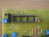
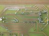
I have a problem and i can't understand what kind of problem is that. I made a power supply for my bench. I made two channels 0-30V and one channel -30V-0V. Also i put 0.1ohm resistors to measure the current of all three channels. Then i decided to display the voltages and the currents via 2x20 LCD controlled by a PIC16F877. I transformed the voltages and the currents with op amplifiers to bring them at 5V maximum at the six analog pins of the uC. I wrote the program, i burned the pic, i turned the switch on and the problem is that the LCD displays nothing except if i put my fingers on the pins DB4, DB5, DB6, DB7. Only then the LCD displays and working as i programmed the pic. I drive the LCD with four pins data and not with the eight. 4Mhz clock for the pic. It is the first time i saw this kind of problem at pic-LCD's. Is the problem to the connector? Cold soldering perhaps?
Please help!