Hi. This might be really simple, but I bought a new 3.5 digit 'LCD Panel Meter' today and need some help in wiring it up, as these things aren’t exactly cheap, and I don’t want to connect it incorrectly and ruin it. So I was hoping somebody - who is familiar with them - might be able to help.
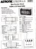
I have attached the data sheet that came with it.
This one is a 12-pin module and they didn’t exactly provide nice examples to work with.
I want to be able to measure DC voltage (only), up to 20 volts. Decimal points = 2.
Also would prefer to use a zener diode instead of a 5V regulator is possible.
I don't understand what some of the pins are for, and how to hook them up
How would one wire this thing up? -- Schematics would be nice, thanks! --
Thanks.
Jason.
Attachments
Last edited: