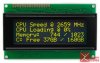
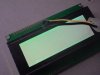
So I order this display from China yellow character anyways after 2 weeks it arrives and I connect the power and I'm not sure if this is how all yellow characters look but it seems nothing like the picture?
is the polarizer the wrong way or something?
is the polarizer the wrong way or something?