Mosaic
Well-Known Member
Hi all:
I am using a 16f886 at 8Mhz
I modded the LCD.bas sample to read:
This fails....it specifically will work if I change the LCD RSREG and EREG to operate off PORTC or PORTA.
Why doesn't the sim permit me to use portb.4 and b.5 as the control lines? It allows A.4, A.5 or C.4, C.5.
I am using a 16f886 at 8Mhz
I modded the LCD.bas sample to read:
Code:
Define ADC_CLOCK = 3 'default value is 3
Define ADC_SAMPLEUS = 10 'default value is 20
Define LCD_BITS = 4 'allowed values are 4 and 8 - the number of data interface lines
Define LCD_DREG = PORTB
Define LCD_DBIT = 0 '0 or 4 for 4-bit interface, ignored for 8-bit interface
Define LCD_RSREG = PORTB
Define LCD_RSBIT = 4
Define LCD_EREG = PORTB
Define LCD_EBIT = 5
Define LCD_RWREG = 0 'set to 0 if not used, 0 is default
Define LCD_RWBIT = 0 'set to 0 if not used, 0 is default
Define LCD_COMMANDUS = 2000 'delay after LCDCMDOUT, default value is 5000
Define LCD_DATAUS = 50 'delay after LCDOUT, default value is 100
Define LCD_INITMS = 2 'delay used by LCDINIT, default value is 100
'the last three Define directives set the values suitable for simulation; they should be omitted for a real device
Dim an0 As Word
TRISA = 0xff 'set all PORTA pins as inputs
ADCON1 = 0 'set all PORTA pins as analog inputs
Lcdinit 1 'initialize LCD module; cursor is blinking
loop:
Adcin 0, an0
Lcdcmdout LcdClear 'clear LCD display
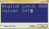
Lcdout "Analog input AN0" 'text for the line 1
Lcdcmdout LcdLine2Home 'set cursor at the beginning of line 2
Lcdout "Value: ", #an0 'formatted text for line 2
WaitMs 1 'larger value should be used in real device
Goto loop 'loop foreverThis fails....it specifically will work if I change the LCD RSREG and EREG to operate off PORTC or PORTA.
Why doesn't the sim permit me to use portb.4 and b.5 as the control lines? It allows A.4, A.5 or C.4, C.5.
Last edited: