Continue to Site

Welcome to our site!

Electro Tech is an online community (with over 170,000 members) who enjoy talking about and building electronic circuits, projects and gadgets. To participate you need to register. Registration is free. Click here to register now.

  • Welcome to our site! Electro Tech is an online community (with over 170,000 members) who enjoy talking about and building electronic circuits, projects and gadgets. To participate you need to register. Registration is free. Click here to register now.

Latching Solenoid Capacitor driver

Status
Not open for further replies.

Water_Dr

New Member
Hello,

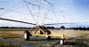
I am building a timmer control for an irrigator and need to control a latching solinoid. I am using latching as the system must be powered by batteries (and I am trying to avoid the additional cost of solar).

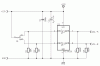
I have many times created simple switched control of the solinoids that require a short pulse + - to latch and a short pulse - + to delatch using a 2200uf capacitor in series to one of the lines and a SPDT to charge (create latching pulse) and discharge (create delatching pulse). I could simply use a SPDT relay to activate the solinoid but am trying to keep the current consumption down.

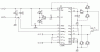
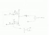
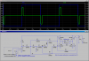
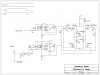
The attached pdf shows the SPDT switch that works fine. The other diagrams shows a transistor arrangement I thought would work but does not. The NPN is a BC547 and the PNP is a BC556. I am no electronics expert and really a novice, but this transistor circuit does not appear to be creating enough pulse as the solinoid only makes a dull thud noise and does not latch, even though the capacitor is charged.

Would some sort of N and P Mosfet arrangement work better possibly?

Any suggestions would be much appreciated.

Regards Blair
 

Attachments

  • solinoid control.pdf
    312.6 KB · Views: 391
What is the capacitor supposed to be doing? Are you saying that your circuit "works fine" with that capacitor in place??? Put in some diodes to protect the transistors against inductive kickback from the solEnoid. How much current does your solEnoid draw? What is the battery voltage? Are you biasing the transistors correctly (ie, what are the base resistor values)? What is your control signal? If it is a manual switch, I dont see the point of having the circuit. Are you using a microcontroller and sensors? A better latching switch might comprise an SCR.

Most irrigation solenoids require at least 12 volts, usually closer to 24, especially if there is a lot of water pressure to control. If your system uses full pressure from the water utility and a sprinkler system solenoid valve, make sure your voltage is high enough!!
 
The switch version draws no steady-state power; the transistor version unfortunately does.

What drives the transistor bases?
 
Hi

Thank you for your replies. I will try and elaborate and answer your questions the best I can as I am a beginner at this stuff.

The project goes like this. When a travelling irrigator gets to the end of the paddock a micro switch is activated turning on power to the project. A solinoid is to be activated to open a valve to operate a small sprinkler from the time it hits the end of the paddock until a preset time. I had thought the switch would act directly transister pair base to start this one.

A timmer (LS7212 seems to work well on bread board with the exception of a short pulse on power up which I have not figure out how to deal with) will count down a set number of minutes (say 15) and then activate another solinoid that will operate a valve that fills a hydrailic piston closing the large main water feed to the machine. The timer will set its output port high when the delay period is complete. Again I thought this would act on a pair of transistors to activate the capacitor circuit.

The circuit is 12v and the latching solinoids are designed for 9-12v operatation as appose to mains supplied systems that use 24VAC for the solinoids.

When the capacitor is discharged and the switch is shut feeding 12 volts into it passes a pulse through to the solinoid and it latches. My understanding is that no more current is required other than this initial pulse and charging of the capacitor. When the SPDT switch is moved to the other position the capacitor discharges and creates a pulse in the other polarity to the initial pulse and this resets the solinoid.

I could use a SPDT relay but was trying to get away from the large holding current for this, but I suspect I may have to revisit it.

In terms of base resistor, I have tried all sorts, but with no luck, The last attemps was about 500R. I was just feeding 12v or G into the bases of the pair of Transistors by moving a wire around on the breadboard for now.

Since posting the original port I went out and got a couple of mosfets. 1 P-Channel and 1 N Channel. I managed to get the circuit to work with the exception of not being able to common the gate lines to operate of one input signal. I have from each gate a 1M resistor to high for the P-CHannel and low for the N-Channel and 10R in series to the gate. It was at least passing enough current quickly enough to generate a pulse that would operate the solinoid. I am guess when operating them on the same control line (again just moving a wire from G to 12V to trigger) that they are both on at one stage and dampen the pulse to prevent it operating. The capacitor does charge upto 9.5 volts (battery 12.2) but only discharges down to 3.0 volts when the drain mosfet is activated. Not sure if this matters or not.

Anyway, I am not sure if that is any clearer,

Regards Blair
 
What is the Ohmic resistance of the pulsed coil? How many volts is the coil rated for? You are operating the circuit on 12V, right?
 
The coil is 12 volt rated. I only measure about 5 ohms accross the 2 wires, but not sure how these latching solinoids operates so unsure if that is accross the coil (coils? as think there is actully 3 inside.
 
I think your problem is when the input signal is neither high or low but floating. In this condition both transistors are on. Maybe you can show us what the actual control switches look like?
 
Hi Ronv

I have tried to draw what I had working last using Mosfets (I blew it all up and pulled it to pieces before drawing what I had but I think I have the Source and Drains around the correct way - never tried mosfets before - I have a burn on my finger to prove it :-( ).

When it was working (not actually certain why it stopped and got all hot and bothered) I could latch and delatch the solinoid happily by applying 12volts to the 10 ohm resistor on teh N-Channel Mosfet and then delatch by applying Earth to the 10 ohm resistor on the P-Channel.

When I altered as per attached excert to essentially common the gate series resistors to one point and toggle from 12v to G I could not get it to latch or delatch.

Does this make it a little clearer?

Thanks Blair
 

Attachments

  • Mosfet Circuit.JPG
    Mosfet Circuit.JPG
    12.2 KB · Views: 435
Sure, that confirms it. Once you tie the gates together the 2 1 meg resistors form a voltage divider and you end up with 6 volts on each gate which probably turns both on. Bet they did get hot. I can only guess that in your actual application you can't have it like your shematic where the gates are separate?
 
Maybe we can walk through your application. Start--- travel to the "end" and turn on a switch which you would like to turn on the valve. So this is a normally open that puts +12 to the gate of the NChannel fet thru say 500 ohms when activated. This would latch the valve. Does this also reverse the machine? If it does then the "end" switch would open and the timer would start. After 15 mins. the timer output goes high. This would need to be inverted to drive the P channel fet. Is this the end until something starts it over?
 
Hi Ron,

OK lets start at the begining.

I have attached a picture of the machine.

These irrigators use water pressure to rotate the boom which acts on a winch and tows them accross the paddock.

When the get to the end of the paddock the machine hits an end stop that puts them out of gear and they sit watering on the same spot until the farmer arrives to shut them down which is incrediable wastefull of power and water. In saying this they need to water on for a while as the rear of the machine has not passed over the front half of the watering circle so the front has only been half watered.

As 90% of the water comes out of the drive nozzels on the end of the boom (angled backwards to drive the boom in rotation) when it is sitting at the end of the paddock you need to to rotate for a long time to ensure the inside of the donut gets enough water. To improve the effieciency I plan to add a small sprinkler on the machine facing backwards and a slightly larger one on the from facing fowards and run these while it pauses at the end to speed up watering the inner donut. After say 15 minutes (at present upwards of an hour if the farmer is around) the machine can be automatically shut down.

Ideally as there are stock in there paddocks often I am trying to avoid solar power as it is hard to protect the panels in this situation and it adds cost.

Operationally:

The farmer moves his irrigator to a new part of the farm and tows a rope to the end of the paddock. Near the end of the paddock the rope has a stopper clamped to the rope. When the farmer returns to the machine he pulls out a large arm along the rope that is attached to the machine and engages the gear box (Galvanised bit at the front of the machine in the photo).

Attached to this arm is going to be a bungy cord attached to a SPST momentary off switch so when the arm is forward and the machine moving power is cut from the circuit.

When the machine hits the end of the run and the shaft moves back diengaging the gearbox the SPST switch is released and powers up the circuit.

I plan to do something with this power circuit so that when all the timing/valve operation is complete the power is cut from everything to save power loss when sitting idol. I have some ideas but still a work in progress (like this whole project).

When power first arrives at the circuit two things are to happen.

1. A solinoid is latached to activate the valve connected to the front and back small sprinklers. The capacitor will only need to be charged here to latch the solinoid as a manual push button can drain the capacitor when setting up for the next run to delatch the device as eventually all water will be cut from the machine so it will not matter if the solinoid is left running. There is no current consumption one the pulse has occured and the capcitor charges. So to achieve this the SPST momentary off switch can feed 12v directly to the + side of the capacitor and the solinoid will activate.

2. A timmer starts counting the predefined minutes to wait before the main water supply to the machine is turned off. Currently I have tested a LS7212 timmer that allows me to set 8 dip switches to determine the run time. I am using a crystal and it seems very accurate. The only issue i have at present is when it powers up there is a 1 second roughly positive output on the output pin. This would potentially latch and delatch my solonoid for a short period. Given the valve the solinoid will operate will take around 30 seconds to shut this will probably not cause an issue unless the period of this positive swing is so short it fails to latch and delatch the solinoid creating issues with latching it latter in the sequence.

When the timer reaches say 15 minutes the output is set latching the solinoid and filling the ram in a actuator that shuts the 4 or 5 inch butterfly valve on the main hose (water to the samll sprinklers comes off downstream of this point so they will stop as well). Again now thinking about it as with the small sprinkler solinoid it can stay latched until the farmer returns to set the machine up again and he can then manually delatch the solinoid with a push button. This would remove the need for the second Mosfet. But for it to work I would have to get around the positive pulse when the timmer powers up.

At this point I thought the positive trigger would also start another timmer, maybe just a 555 this time to send a signal to some self lathed relay arrangement (after the water is off) on the main power supply to kill power to the whole circuilt. Not sure how yet but some form of relay contacts feeding power to the relay coil through the NO contacts to maintain its power. This would interrupted by momentarily turning on the power to a NC relay that feeds this self latching relay.

I hope this make some sense and you have not lost interest by the time you get to the bottom of this. It all seemed a good idea when a friend who has 5 of these irrigators asked me if I could help him make them work more efficiently. I work here in NZ as a irrigation managment consultant and if I can get this sorted I will be able to help a lot of my customers reduce the environmental effects of their operations.

Thanks Blair
 
Attached is circuit which will Latch/Unlatch your latching relay based on a simple contact closure, or a logic signal. The power supply drain between pulses is minimal. The peak current through the coil during the pulse is ~2.5A. The pulse duration can be adjusted with R2-C2. The P and N Fets are not critical; they need to be rated for ~25V @ ~3A.
 

Attachments

  • DF48.png
    DF48.png
    50.5 KB · Views: 344
Last edited:
Sprinkler

I think I understand what you have. It runs until it gets to the end then you trip a switch (I call it + End). This turns on the small sprinklers for 15 minutes then off with minus timer. (may have to put an inverter in this line to make it compatible with what is now plus timer)
I think something like Mike posted would be better than the capacitor. However that circuit won't work with your inputs. Here is a similar circuit with a little timing diagram to confirm the function. Mike could probably break the single input into two for you if you prefer that circuit. In either case I think the timer glitch has to be fixed. You might drop the reset with the switch instead of applying power with it. The whole thing will probably run with less than .001 amps so if you used a little lead acid battery you could probably get 6 months between charges. (I'm guessing this is what you were going to use since you said 12 volts) Let us know if the timing is correct.

PS. Are you still in a drought?
 

Attachments

  • latch2.PNG
    latch2.PNG
    102.9 KB · Views: 480
Mike and Ron,

Thank you very much for your efforts. It is really appreciated. Its Monday night here now and my working week is now in full swing (not got a 8 hour a day job worse luck) so this is going to take a back seat for a few days, but I will come back with questions if thats is all right once i have had time to try and digest your sketches. This will be a big job for me as an amature but looking forward to the challange as I am in sorting this problem.

Thanks again Blair

PS Ron, drough has been a big issue in the north this year, but the winter has been very wet, especially in the south island (my area - Canterbury if you know it) in recent months so the drought is broken.
 
Hi Water_Dr,

here is an easy solution:

Use a dual high speed MosFet driver.

The switch is springloaded in the neutral position.

Toggling it either side will latch/unlatch the solenoid.

Function: Inputs A and B "see" ground via the pull down resistors R1 and R2. This keeps outputs A and B low (ground).

When the switch is thrown towards input A - output A becomes positive while output B remains zero (ground potential). (e.g, latching).

Releasing the switch the solenoid remains latched with no current flow across the coil.

Unlatching works vice versa.

The suggested PCB layout measures 38X33mm.

Regards

Boncuk
 

Attachments

  • LATCHING-SOLENOID-SCH.gif
    LATCHING-SOLENOID-SCH.gif
    13.2 KB · Views: 601
  • LATCHING-SOLENOID-BRD.gif
    LATCHING-SOLENOID-BRD.gif
    18.7 KB · Views: 375
...Use a dual high speed MosFet driver....

The MC34151 is only rated to source/sink 0.4A. The OP's solenoid requires 2.5A.
 
The MC34151 is only rated to source/sink 0.4A. The OP's solenoid requires 2.5A.

My data sheet says sink or source 1.5A.

It will probably suffice for short pulses, even if the chip is overloaded.

On the other hand - if it's too weak - make it stronger. :)

That one can stand 2.8A sustained and 5.6A peak
 

Attachments

  • LATCHING-SOLENOID-1-SCH.gif
    LATCHING-SOLENOID-1-SCH.gif
    15.6 KB · Views: 382
  • LATCHING-SOLENOID-1-BRD.gif
    LATCHING-SOLENOID-1-BRD.gif
    21.9 KB · Views: 279
Last edited:
Hello Boncuk (and everyone kindly helping me with this project),

Thank you for your idea. The single IC is appealing if it is indead able to supply the required current. I just remembered my friend at the landscape irrigation shop (these are they guys who use these latching solinoids) loaned me 2 models. I just checked the second and found it is 9.6 ohms so the current problem is probably sorted.

I am concerned that the current consumption in idol looks very high for this application.

TOTAL DEVICE - Power Supply Current - Standby (Logic Inputs Grounded) 6mA

But if the whole system is off for 23 hours per day then this is probably not and issue still.

I will need 2 of these circuits. The first to run the solinoid for the small sprinklers when the machine hits its end stop.

I need to create a pulse on initial power to the circuit when it reaches the end of the run to start the sprinkler.
After my LS7212 timmer completes its count down send a pulse to latch the second solinoid and start closing the main valve shutting of the main water supply.
Ideally then to make it simpler for the farmer I would then delatch both solinoids (after say 1 minute to allow the valve to shut - the main valve is one way and will not reopen) and then with some kind of break to the supply to a self latching relay so it looses its latch turn power of to the whole circuit.

Forgetting the depowering issue for now can you (or Ron?) maybe suggest how I achieve this. In reality in the application I will not have a switch other than the SPST that indicates the machine has stopped and the process must start. I have not had time to fully digest Rons circuit but he TS556 looks like it will provide the pulse so maybe I can use this type of arrangement.

Anyway. will study in more detail this evening as have to go to work now.

Regards and thanks Blair
 
Status
Not open for further replies.

New Articles From Microcontroller Tips

Back
Top