Continue to Site

Welcome to our site!

Electro Tech is an online community (with over 170,000 members) who enjoy talking about and building electronic circuits, projects and gadgets. To participate you need to register. Registration is free. Click here to register now.

  • Welcome to our site! Electro Tech is an online community (with over 170,000 members) who enjoy talking about and building electronic circuits, projects and gadgets. To participate you need to register. Registration is free. Click here to register now.

laser trip wire, I need help and I'll pay

Status
Not open for further replies.

beochie

New Member
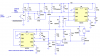
Sorry for yet another one of these threads but... I want to build a laser trip wire. Every thing ive seen has info. missing, or I need to program a pic.

This is what I want to have happen: when the laser(from a pen) is broken I want to spin a 9v motor untill the beam is re connected.

If the beam is broken for just a fraction of a second I would like the motor to spin for about .5 second.

I would also like it if I could controll how fast the motor spins.

I'm trying to keep this cheap and simple. I can read schematics but other than that im basically dumb at this.

I'll paypal some $ to the person that posts a good schematic. o

oh and please dont bash others ideas inless it's really necesary.
 
To control how fast the motor spins, you need some kind of feedback, which just pushed the price of your project past $20. YOu also need a motor driver (which you may not want to build yourself, especially if it's a small motor since they are really cheap. Just look at Polulu robotics or some other place like that- that's probably at least $20. Or you could build an H-bridge if you are want to really skimp on money.
https://www.modularcircuits.com/h-bridge_secrets1.htm

The rest basically has to do with connecting a photo-diode or transistor to the pin of a PIC and detecting when it goes low (indiciating not enough light shining on it) and coding it to do something when it does. Hooking up a PIC only takes a resistor to pull the clear or reset pin high, a voltage regulator, and 2 or 3 capacitors to bypass the voltage regulator on either side and the power pins of the PIC. And maybe a crystal and a couple more resistors and capacitors for a clock if the PIC doesn't have an internal oscillator.

TO program a PIC you need an a piece of hardware called a programmer like the ICD2 or inchworm or something. YOu could try using the picaxe too which is made to need only two wires be minimal for small classroom size projects. The software can be found free in either case from the Microchip website for (PIC) or the picaxe website (for picaxe).
 
Last edited:
beochie said:
I'm trying to keep this cheap and simple. I can read schematics but other than that im basically dumb at this.

I'll paypal some $ to the person that posts a good schematic.

and cant I use something like a light dimmer to adjust speed?
 
There is a difference between controlling the speed ("I want it to go this fast no matter what load it is under") and adjusting the speed ("let's have it go a bit slower or faster". Which one did you mean?

You can use a potentiometer (variable resistor) to slow down the speed of a brushed DC motor. If it's a AC light dimmer, make sure it's just basically a potentiometer- not some voltage chopping device which is not compatible for a DC motor (or DC anything). It's easy, but wastes power.

if you care about power, you should build an H-bridge and use PWM. You can have the PIC change the PWM to the H-bridge through code, or external keypad, or potentiometer acting as a voltage divider feeding into the PIC's ADC, or you can just build a completely separate 555-timer circuit so you can change the speed yourself by turning the potentiometer's knob.
**broken link removed**

All these methods I have mentioned are "adjusting the speed". Not "controlling the speed", since that needs feedback. To control the speed, you need to use PWM with the PIC, and have something sending the speed to the PIC. The PIC then controls the PWM to keep the motor at the right speed- it's pretty simple, but much more complicated and expensive than simply adjusting the speed with a variable resistor.

The cheapest, most inexpensive method would be to "adjust the speed" with a variable resistor, and use a wall-wart so you don't need to care about wasting battery power through the resistor. It only works for small motors though since wallwarts can't provide an enormous amount of current and variable resistors (small ones anyways) can't dissipate a huge amount of heat.
 
Last edited:
I can tell you from experience, lining up a laser pointer to reflect off a mirror and back to the detector is a major pain in the butt.

What kind of distance are you looking to cover?

For all of the above about motor speed, wouldn't have been simpler to ask what the motor would be doing, then control/adjust/regulate wouldn't be such a mystery.

This seems similar to something from last year, will search and see if I remember right...
 
lol. It truly is a pain in the ass to set up a laser pointer to bounce off a mirror and back. A group of us went to an elementary school to do a laser maze demo and to set up we had to align two lasers and 5 mirrors or so. It took us about 3 hours or so. A large part of the problem was the losses through each mirror weakening to the point where the diode couldn't detect the laser anymore.
 
For simple "there and back" sensors, a molded plastic retroreflector (i.e. replacement tail light lens) is the easiest thing to use. Mirrors are a really bad idea unless you are willing to shell out for the relatively expensive mirror mounts with thumbscrew adjustments and a very stable mount.
 
hi,
For ease of alignment, look at retro-prisms, same type as used by surveyors.
The cheaper plastic versions come in a number of diameters.

The smallest I have used for laser work are 20mm dia and 50mm dia.

They are not cheap compared to mirrors or the 'car' type reflectors, but the cost can be saved in the setup/install time,
also they are also more efficient reflectors.

Eric
 
Hi,

I'm not sure if complete alignment is necessary. I think you should at least modulate the laser signal so that its not effected by ambient lighting (sun, bulbs, flouresant tubes etc..). That way you could make the detector very sensitive. Remember, if YOU can see the laser spot on the wall, then I'm sure a IR detector could, providing its amplified. Some basic optics might be necessary, at the detector, like a convex lens just to narrow its viewing angle to *roughly* where the laser spot will be pointing. And maybe have a white specular reflecting surface (printer paper) to scatter it.

As for the electronics, it wouldn't be too hard to build an IR amplifier/detector, for a specific frequency (your modulating frequency) that simply outputs a 'yes/no' when it detects the beam. That, connected to either a PIC micro, or a simple PWM supply to control the motor (what changes the speed?) would do. There are various circuits on the web for converting a pulse width to a voltage, so that the quicker the beam is broken, then re-established, the lower the output voltage (or visa versa).

Or, for simplicity, just a 555 timer in monostable mode, to keep the motor on for 0.5s regardless of how long the beam is broken for.

It really depends on the application in question. I'm not sure if thats what you wanted/needed, but tis what I'm thinking. Then again, I tend to over complicate things :D

Blueteeth
 
thanks for the help guys, but I dont plan on refelcting any beam(the transmitter will shine directly on the receiver)
the distance will be about about 30 yards
motor is to spin pabble that hits a trigger to shoot a airsoft gun


simple alls I need is a schematic.

I dont want to have to program anything
 
beochie said:
thanks for the help guys, but I dont plan on refelcting any beam(the transmitter will shine directly on the receiver)
the distance will be about about 30 yards
motor is to spin pabble that hits a trigger to shoot a airsoft gun


simple alls I need is a schematic.

I dont want to have to program anything
The point of the reflector is to allow all your electronics to be in one place. Otherwise, you need the laser pointer located remotely from the detector and motor controller. That may be OK with you (?).
 
In that case its even more simple.

Laser at one end. Reciever at the other. Maybe a simple photodiode, with a relay. If the laser is shining on the photodiode (or phototransistor) all the time, then it'll easily distinguish betwen on and off, because lasers are so damn bright. So, phototransistor -> comparator -> transistor -> relay -> solenoid/motor for the trigger.

That could be done on stripboard, very small. Although....heres the clincher, when the laser isn't shining on the detector, it'll trigger the solenoid, so your bb gun will be popping off rounds like GI Joe. Best to align, turn the laser on, THEN turn on your circuit to 'arm' it, otherwise setup will result in casualties :D

Seriously though, I could draw up a schem, but just google for 'light detector', most will use a LDR (light dependant resistor) and a comparator of some kind. I guess you'll have to sort out the mechanism for firing the BB gun, a motor would have to be geared down, and then rigged to a lever to have the torque to pull a bb gun trigger. I recommend a simple solenoid, it'll also be quicker.

UNless of course your 'bb gun' is one of those electric jobs? in which case just replace the trigger switch with a relay and jobs a goodun :D

Blueteeth

Ps. This isn't some student gag to stop flatmates enetering your room is it? I will not be responsible for 6mm bruises!
 
Blueteeth said:
In that case its even more simple.

Laser at one end. Reciever at the other. Maybe a simple photodiode, with a relay. If the laser is shining on the photodiode (or phototransistor) all the time, then it'll easily distinguish betwen on and off, because lasers are so damn bright. So, phototransistor -> comparator -> transistor -> relay -> solenoid/motor for the trigger.

That could be done on stripboard, very small. Although....heres the clincher, when the laser isn't shining on the detector, it'll trigger the solenoid, so your bb gun will be popping off rounds like GI Joe. Best to align, turn the laser on, THEN turn on your circuit to 'arm' it, otherwise setup will result in casualties :D

Seriously though, I could draw up a schem, but just google for 'light detector', most will use a LDR (light dependant resistor) and a comparator of some kind. I guess you'll have to sort out the mechanism for firing the BB gun, a motor would have to be geared down, and then rigged to a lever to have the torque to pull a bb gun trigger. I recommend a simple solenoid, it'll also be quicker.

UNless of course your 'bb gun' is one of those electric jobs? in which case just replace the trigger switch with a relay and jobs a goodun :D

Blueteeth

Ps. This isn't some student gag to stop flatmates enetering your room is it? I will not be responsible for 6mm bruises!
You need a monostable that fires when the beam is interrupted.
EDIT: Rereading his post, it looks like he wants to go fully automatic when the beam is broken, . A monostable could give him a burst.
 
Last edited:
beochie said:
If the beam is broken for just a fraction of a second I would like the motor to spin for about .5 second.

that would be full auto for .5 seconds.
No schematics? whats up with that? I thought this would be a walk in the park for someone
 
beochie said:
that would be full auto for .5 seconds.
No schematics? whats up with that? I thought this would be a walk in the park for someone


Ahh so you *expect* a nice neat schematic drawn up? If you googled, and have access to a calculator, you could have your own schematic within an hour. Its all very well someone spending their time making up a schematic and parts list for you, but this is a place of learning, and you won't learn very quickly that way.

Google '555 timer monostable' and you'll find your schematic. The output should drive a transistor, which in turn, drives a relay.

What experience do you have in electronics?

I may draw up a schem for you but I'm not sure many people would simply answer requests like that.


Blueteeth
 
Here's a basic schematic with no speed control. No guarantees. Not tested. Not even simulated.

EDIT: Speed control added. Same caveats apply. :D

EDIT: made a couple of corrections.
 

Attachments

  • laser trip wire.PNG
    laser trip wire.PNG
    20.9 KB · Views: 256
  • laser trip wire with motor speed control1.PNG
    laser trip wire with motor speed control1.PNG
    37.3 KB · Views: 267
Last edited:
I dont quite understand the arrows --> are they suposed to meen ground? and why 2 wires going to the motor? in the first pic? Thanks a ton for the effort
 
beochie said:
I dont quite understand the arrows --> are they suposed to meen ground? and why 2 wires going to the motor? in the first pic? Thanks a ton for the effort
Connect all the arrows (ground symbols) together. Also connect the negative terminal of your power supply to ground.
Not sure what you mean about the two wires to the motor. A motor will not run on only one wire.
Let us know if it works.
 
No offence intended beochie, but if you have to ask such questions then you might not be expreianced enough to build this circuit.
 
lol, Ron, I draw up a schem a couple of days ago, and just realised its almost identical to yours in every way :D The phototransistor, comparator, the rising edge trigger circuit and the 555...even down to the values used for the timer!

I would say 'great minds think alike' but that would probably drag you down to my level..so glad I didn't post it now.

Blueteeth
 
Status
Not open for further replies.

Latest threads

Back
Top