Electro Tech is an online community (with over 170,000 members) who enjoy talking about and building electronic circuits, projects and gadgets. To participate you need to register. Registration is free. Click here to register now.
Welcome to our site! Electro Tech is an online community (with over 170,000 members) who enjoy talking about and building electronic circuits, projects and gadgets. To participate you need to register. Registration is free. Click here to register now.
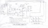
Sorry for the messy drawing, but this is how I have it attached (i think ). Is there some program you use for drawing circuits? Thanks again, you have been so very helpful.
The datasheet for the laser sensor says the Current Load Voltage Output is <1mA. I assume this means that the sensor outputs a current of <1mA when in analog voltage output mode (there is also a current output mode). Would this current be low enough for the circuit to work?
I hooked up the laser to a different power supply and the circuit seems to work very well. I will need to do a bit more testing before I figure out if it has changed the range or response of the sensor at all. But this is quite encouraging. Thanks!
I hooked up the laser to a different power supply and the circuit seems to work very well. I will need to do a bit more testing before I figure out if it has changed the range or response of the sensor at all. But this is quite encouraging. Thanks!
hi Dan,
Did you check that link I posted ref the NMA2412 dual dc to convertor/isolators.?
Farnell Products
You could mount one of those on the OPA pcb and use a common 24Vdc supply for the Laser and OPA pcb.
The input resistance of the OPA with that 47K/47K divider is say 100K,
so with a +10Vdc input the current drawn from the laser is only 100 micro-amps.!
I checked at the electronics depot here at the University, and they either don't have the part or they are extremely unorganized. I am going to buy the DC/DC converter online, so it will be a week or so before I get to try it out. Otherwise the circuit seems to work well.
So your saying that the Supply for the laser should be +12V and 0V? I tried this and it seems to work, but the specifications for the laser say a supply of 18V to 24VDC should be used. What is the significance of using 12V instead?
So your saying that the Supply for the laser should be +12V and 0V? I tried this and it seems to work, but the specifications for the laser say a supply of 18V to 24VDC should be used. What is the significance of using 12V instead?
I installed the dc/dc converter and it works great! I also tested the linearity of the measurement range and it appears virtually unaffected (by the level shift circuit). This is all very good news. Thank you so much for your help!
This site uses cookies to help personalise content, tailor your experience and to keep you logged in if you register.
By continuing to use this site, you are consenting to our use of cookies.

") ). Is there some program you use for drawing circuits? Thanks again, you have been so very helpful.
). Is there some program you use for drawing circuits? Thanks again, you have been so very helpful.