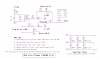
I am a Civil Engineering student and I am working on a project using a laser sensor which outputs a voltage between 0 to 10V (depending on displacement measured). However, I need to feed the range into a DAQ board (Data Acquisition) and it requires a range of -5V to 5V. Is this any easy fix with a circuit? Or is it more complicated than it seems? Help please, I don't know much in the way of electronics!
Continue to Site
")