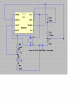
I think the simulation program is stupid.why when I simulate this circuit - two LEDs connected to 555 output, the LED to ground shows current flow but the LED connected to Vcc to pin 3 output shows no current.
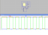
why doesn't it show current when the 555 output goes low?
maybe a reference to ground?? issue.
When the output of the 555 goes low then the upper LED should light.
When the output of the 555 goes high then the lower LED should light.
The simulation also shows an output voltage that is too high when the output of the 555 is high.