I have a problem with PWM controller.
original thread about it here: https://www.electro-tech-online.com/threads/need-help-with-pwm-mosfet.88471/
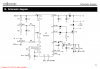
I use velleman K8004 PWM controller card to drive DC motor.
DC TO PULSE WIDTH MODULATOR
Manual:
https://www.electro-tech-online.com/custompdfs/2010/08/illustrated_assembly_manual_k8004_rev3.pdf
I have Canon Printer Carriage Motor QK1-1500
TN425813 12V DC.
**broken link removed**
**broken link removed**
**broken link removed**
I control the motor via 1K pot. I use internal reference voltage to control the motor speed. But as the load changes so does the motor speed.
How can I adjust the speed like I do now via POT but be able to lock it?
Please see manual page 8 for connection options.
I have the timing disc and 4 contact sensor (hall sensor?) from Canon printer that I could use. Or is there another easier way?
Thank you.
original thread about it here: https://www.electro-tech-online.com/threads/need-help-with-pwm-mosfet.88471/
I use velleman K8004 PWM controller card to drive DC motor.
DC TO PULSE WIDTH MODULATOR
Manual:
https://www.electro-tech-online.com/custompdfs/2010/08/illustrated_assembly_manual_k8004_rev3.pdf
I have Canon Printer Carriage Motor QK1-1500
TN425813 12V DC.
**broken link removed**
**broken link removed**
**broken link removed**
I control the motor via 1K pot. I use internal reference voltage to control the motor speed. But as the load changes so does the motor speed.
How can I adjust the speed like I do now via POT but be able to lock it?
Please see manual page 8 for connection options.
I have the timing disc and 4 contact sensor (hall sensor?) from Canon printer that I could use. Or is there another easier way?
Thank you.
Last edited:
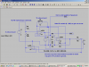
 I can't simulate this as parts are missing from my simulator and don't wan to damage already working PWM controller.