Electro Tech is an online community (with over 170,000 members) who enjoy talking about and building electronic circuits, projects and gadgets. To participate you need to register. Registration is free. Click here to register now.
Welcome to our site! Electro Tech is an online community (with over 170,000 members) who enjoy talking about and building electronic circuits, projects and gadgets. To participate you need to register. Registration is free. Click here to register now.
That's for programming any ICSP PIC. That's what a programmer is for. The onboard 1320 is just a convience. No cable needed because the wires are on the board. Don't forget to change over the top 3 dip switches from Tutor to Programmer.
I've programmed lots of different PICs with it. You just put 5 pins on your breadboard in the right order, or buy a 2x5 socket and rig it for same. I use the quick & dirty 5 pin method. Have to get in a habit of doing it the same way every time so I don't plug it in backward, though I doubt it would hurt anything.
You can probably buy a cable somewhere. I make my own from old computer serial cables. The old 486 and older boxes all had at least one 2x5 plug and 10-conductor ribbon cable each (some were 9-conductor, so pay attention). Lots had two of these cable assemblies.
I cut off the serial or parallel connector, carefully disassemble a 2x5 plug from another cable and reassemble it on the other end of the ribbon. You'll need one or two tiny jeweler screwdrivers, some patience, good eyesight and lots of light. You'll probably destroy the first one or two you try before you figure out how they come apart. Takes sort of a delicate touch. Pry just enough to get it apart. Too far and it breaks.
Pay attention to where pin-1 is. Assemble so that the ribbon comes off the plug the right way. I always get em wrong and have to fold it back.
Some of the connectors have one hole plugged to key them. Some are just a simple plastic hole plug you pry out. Some have epoxy or some kind of glue over the plastic plug. Dig that out and the plug comes out easily.
I have a box of those old connectors. I always pick up ancient computers when I see them getting tossed out and gut em for the connectors. There are **broken link removed** in there too.
That connector allows you to program target PICs, it's called and IDC connector and is the smaller brother of the ones used on IDE hard drives. It's documented in the Inchworm+ manual and the Inchworm Quick Project poster. The genuine ICD2 uses a RJ12 not easy to breadboard, a genuine PICkit 2 uses a 6 pin inline socket like one on the top of the Junebug expanded for advanced users who want to write their own 18F2550 USB firmware, many ICD clones like Olimex use a 6 pin plug building those cables is a drag and not very robust, but I chose a common 2x5 connector for its robustness and pinned it out to be breadboard friendly can be assembled in a small vice. **broken link removed**
A genuine PICkit 2 connected to a breadboard **broken link removed**
from the Olimex site showing off some different ICD connectors and adapters. **broken link removed**
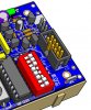
Here's a Junebug programming a Mongooses' PIC18F2525
You could also use the port with the FireFly board to program microcontrollers in a ZIF socket (or build your own ZIF socket board if you just want the ZIF part).
You could also use the port with the FireFly board to program microcontrollers in a ZIF socket (or build your own ZIF socket board if you just want the ZIF part).
Not if you're done prototyping, need to program more than a few microcontrollers at one time (obviously with the same code) and have no need for an ICSP header on the final product -- it's REALLY handy then! Especially with the "one button" programming feature of the JuneBug.
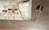
To add to all the pictures, here is a pic of what I use for my ICD2. It is a PCB mount RJ12 jack with #22AWG wires soldered to it which plug into the breadboard with tinned ends. It allows me to quickly isolate the ICD2 from the circuit under development by unplugging the ICD2 patch cable.
Oh what the heck. This first pic came out so pretty I decided to post it here.
My new (2nd) **broken link removed** Just finished soldering it together. Not too shabby for a 0.8 second hand-held exposure. Not enough light to get enough depth of field to get that LED focused.
Looks great Futz, I was surprised how many Unicorn owners cut and jumpered the trace for the LED. If you've got a spare 2x16 LCD try out the Swordfish Christmas LCD program posted in the **** Chat section and also in the December 2007 update on my site.
And I'm surprised you don't put simple instructions for (optionally) doing it in the docs (for the fearful newbs ). I've assembled other companies' kits where they gave details for a fix like that on the board (sometimes multiple fixes). C'mon, do it!
If you've got a spare 2x16 LCD try out the Swordfish Christmas LCD program
I've got lots of spares. One brand wouldn't even light up. The blue one from DipMicro lights up but displays nothing. The problem may be that I don't have a 25K trimmer. Only a 10K stuffed in the holes loose. If I turn it all the way CW I can faintly see blocks but no text.
I played with jumpering with a wire, but still nothing.
Slightly off topic but I noticed on that LED wiring fix close-up picture that there's a bunch of flux left on your board. Don't you clean up and remove the flux using finger nail polish remover or something similar? I actually use an Aqua-Core solder which cleans up quite nicely with warm water and an old tooth brush.
Slightly off topic but I noticed on that LED wiring fix close-up picture that there's a bunch of flux left on your board. Don't you clean up and remove the flux using finger nail polish remover or something similar?
I've been lazy about cleaning new boards lately. I used to clean every one spotless. Guess I should start doing it again before my boards start "growing fur".
I've got lots of spares. One brand wouldn't even light up. The blue one from DipMicro lights up but displays nothing. The problem may be that I don't have a 25K trimmer. Only a 10K stuffed in the holes loose. If I turn it all the way CW I can faintly see blocks but no text.
I played with jumpering with a wire, but still nothing.
Hehehe! I finally disconnected everything, pulled the LCD and really looked the board over closely. Turns out I missed soldering one pin on the MCU. Soldered it up and she works! Contrast is crappy with that 10k pot, but good enough to see it.
I just noticed that you can see it in **broken link removed**.
10K should be fine, some LCDs require negative voltage for decent contrast. On the other hand many GLCDs have their own negative voltage contrast generator that's why for GLCDs you need to remove the jumper.
The LCDs I use are from TopWayDisplay and work great with a positive contrast voltage.
Here's something to try, with the Unicorn jumper removed there is no connection between the CCW wiper on the pot, you could try putting a small 1.5v watch battery between GND and the pin so the pin would be at -1.5V giving you an extended contrast range.
Or fancier something like this... **broken link removed** **broken link removed**
This site uses cookies to help personalise content, tailor your experience and to keep you logged in if you register.
By continuing to use this site, you are consenting to our use of cookies.

 The onboard 1320 is just a convience. No cable needed because the wires are on the board. Don't forget to change over the top 3 dip switches from Tutor to Programmer.