Continue to Site

Welcome to our site!

Electro Tech is an online community (with over 170,000 members) who enjoy talking about and building electronic circuits, projects and gadgets. To participate you need to register. Registration is free. Click here to register now.

  • Welcome to our site! Electro Tech is an online community (with over 170,000 members) who enjoy talking about and building electronic circuits, projects and gadgets. To participate you need to register. Registration is free. Click here to register now.

JK Flip Flop Question

Status
Not open for further replies.
Hi All,

I have build a circuit using crocodile clips, and I have used a JK Flip Flop, however, my local electronics store only sells a Dual JK flip-flop.

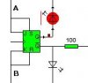
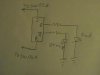
I have the following circuit, to what pins do I need solder to make this circuit still work :oops:

The flip flop i can buy:
https://www.electro-tech-online.com/custompdfs/2004/09/CD4027BCPDF.pdf

Now with the attached circuit, when I pulse 5v+ at point A, the red LED comes on and stays on. If I pulse 5v+ at B, the red LED turns off, and the green LED turns on. This is all i'm trying to acheive so if theres an easier way please let me know, but I'd like to work this out as well :D

Thanks all in advance, :wink:

Tim.
 

Attachments

  • jkflipflop.jpg
    jkflipflop.jpg
    4.4 KB · Views: 969
In your circuit:
J = pin 10
k = pin 11
s= pin 9
r= pin 12
q= pin 15
q(bar)= pin 14
pin 16 = +voltage
pin 8 = gnd

Thats the relationship between the circuit and the FF.
however, all you are using is the set and reset, of the FF, you dont even need to connect j and k to the circuit.
 
ok if you connect the ckt as shown it should work fine. :D

no connection is needed to J or K inputs.
 

Attachments

  • 001.jpg
    001.jpg
    6.7 KB · Views: 886
Instead of Jk FF

The other circuit is known as Bistable Multivibrator which uses switching
Transistors for doing the same thing.In place of jk SR flip Flop can also be used.However Digital circuits are easy to manage.
 
Hmm well I couldn't get it to work properly (or at all) I wonder if I have blown it up..

I put about 14.4 volts to pin 16, and 5v regulated to pins 9 and 12 alternatevly and the LED from pin 14/15 did not light up.

No biggie if I've blown it up but is there an easier/cheaper way to do this or should I use the same circuit just a different way.

Thanks in advance, :)

Tim.

P.S: Can relays work from 12v- as well as 12v+??
 
Looking at the datasheet, you shouldn't have hurt it.
pin 16 can go from -.5V to +18V (max) and then the input pins can range anywhere between 0V and the voltage on pin 16.

What sise resistors did you use for the leds? Even though you put 14.4V on pin 16, the voltage coming out of the output pins is only 5V (I think).
 
they had 470ohm on them, changed to 360 and they can both be seen on very dimly, unless I put either the S or R pins to 5v then the both go bright..

Any ideas?
 
Both LED's turn on when you bring just one of the inputs high?

I looked at the datasheet again, I think it says that if you are running Vdd (pin 16) at 15V, then your High level input has to be at least 11V, and the low level input has to be below 4V.
maybe try connecting pin 16 to your +5V supply?
 
why cant you just use your +5 regulated supply on it?
 
letsrelaythat said:
I put about 14.4 volts to pin 16, and 5v regulated to pins 9 and 12 alternatevly and the LED from pin 14/15 did not light up.

A 40-series can handle up to 15V supply, so it shouldn't be damaged.
But the input voltage levels for a logic 0 and 1 are dependant on the supply voltage. If you feed it 15V (14.4) then a logic 1 starts from 11V and higher. applying 5V to an input will be considered a logic 0.

Also check the maximum output current for the family (CD) you want to use. Most 40- families don't like drivingleds directly... (they will do it but die an early death by doing so)...

letsrelaythat said:
P.S: Can relays work from 12v- as well as 12v+??

Depends on the relay, does it have a + and - input then no, if it hasnt then yes...
 
Well the relays are just standard automotive relays, I was hoping to use them with my power windows, which have 12v- to the motor on the way down..

As for the flip flop, the specs are in the link in my first post.. I'm probably going to have to go out and buy all the bits again, so if I need transistors etc can someone make a schematic with everything I should use??

Thanks in advance, :)

Tim.
 
letsrelaythat said:
Well the relays are just standard automotive relays, I was hoping to use them with my power windows, which have 12v- to the motor on the way down..
So the -12V will go trough the contacts? I assumed it was to feed the coil.
In that case there's no problem at all, the contacts are just mechanical switches, they don't care about + and - :)

letsrelaythat said:
As for the flip flop, the specs are in the link in my first post.. I'm probably going to have to go out and buy all the bits again, so if I need transistors etc can someone make a schematic with everything I should use??

I need more info to draw you a scematic. What voltage will you be feeding the 4027 from (14.4?, or do you have 5v available?). Is this a clean regulated power supply? Where do the input signals come from? (a switch, or another circuit?).
 
Ok well what happens, is when I arm my car alarm, it pulses the 12v+ out 2 wires, 1 for lock and one for unlock. What I am planning on doing id making the alarm cut the ACC and ON wire, and also after the cut in the on wire I am putting in a turbo timer, hence my timer post in the Electronics Design/Reviews area..

I also want some form of visual indication if the flip flop is on armed or disarmed status :)

I eventually want to build into the circuit something which when you lock the car, the first pulse will cut the ACC and ON (with turbo timer extension) and start to put the power windows up (if someone is hanging out the window its their own fault), then, if I pulse the lock wire again (by pressing the lock button again) it will stop the power windows going up.

Unlock once will resume the ACC and ON circuits, and the second unlock pulse will roll the windows down.

I know this sounds hard but i have been working on a crocodile clips circuit and it so far is going to plan, I've just moved over to using large capacitors instead of 555 timers.. saves me a bit of money.

Thanks all who can help with circuits/links etc.

Tim.

edit: I have 12v+ avaiable most of the time, the engine will hit about 14.4v when running (max) so I have just boght 3 12v+ voltage regulators.
I will e using these 12v+ as my sources. Thanks!
 
sorry... :oops:
its just it would have saved us all a lot of time if u had stated that in the beginning. :)
what type of car alarm is it BTW..
 
i am afraid i might have crushed letsrelaythat , with my reply .
if i could take it back i would..
we all have bad days

i am sorry
 
Where are you going to get the 15V from, that is the minimum voltage that is required for the input of your 12V regulators?
Before designing or buying, read the datasheet. A 7812 positive voltage regulator is spec'd with a minimum input voltage of 15V. If you bought ten, a few might work with an input voltage as low as 14V.
A 7809 9V regulator will work fine with an input voltage as low as 12V and can be used to power your flip-flop and its inputs.

The 4027 flip-flop can directly drive the LEDs without current limiting resistors when powered from 9V, because the resulting 6mA to 8mA of output current will be well within the max output current rating. Choose "wide-angle ultrabright" LEDs because 6mA to 8mA through ordinary LEDs will make them difficult to see in daylight.
 
Yeah sorry for not telling everyone what I was planning on doing sooner.. I am trying to have this all installed before my friends have any ideas.. I'm also putting in a automatic window controller and turbo timer, these all need this circuit to work.

The main use for it will be to cut my ACC circuit and ON circuit when the alarm is activated, which will integrate with my turbo timer and I am going to make it somehow only wind the windows up if you pres the lock button twice..

I'll get to that hurdle later.. I might even go down PIC road but ill avoid that till i attempt something crazy like climate control or something..

I have a major schematic drawn up in crocodile clips, and I had most of it working, besides the window controller integration with the alarm.. which will be an interesting project.

Back on topic, I think I may have destroyed the flip flop with the relay somehow, so I have bought all of the components again and I will assemble it all nicely so hopefully it will work.

Thanks for all of your help so far,

Tim. :)

*probably coming soon, the window controller problem*
 
Status
Not open for further replies.

Latest threads

New Articles From Microcontroller Tips

Back
Top