Continue to Site

Welcome to our site!

Electro Tech is an online community (with over 170,000 members) who enjoy talking about and building electronic circuits, projects and gadgets. To participate you need to register. Registration is free. Click here to register now.

  • Welcome to our site! Electro Tech is an online community (with over 170,000 members) who enjoy talking about and building electronic circuits, projects and gadgets. To participate you need to register. Registration is free. Click here to register now.

Jeeperz: Room exploring robot in development

Status
Not open for further replies.
S

Souper man

Guest
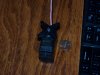
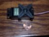
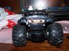
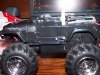
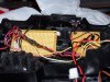
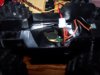
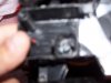
Jeeperz is a room exloring robot that is currently in the works. My only problem is that It is a 2 motor robot, one in the back driving 2 wheels, and one controling the turning in the front. I am going to use a Infrared emitter (4 pairs, aka emitter receiver) and receiver, and use a comparator and compare the receivers. I am then going to send them to a central Comparator, which will then turn the front motor to turn. I dont know how I am going to control the motor turning thing in the front, because I dont know how I would control it to do fine turns. It would just peg out and Jerk real bad. In short, how would I control the Turning motor in front to turn without killing it? PWM?

NOTE: Will get pictures up later today
 
Jeeperz? Never heard of that kind of pasta before... Must be something new.
A servo motor would give you smooth turns, but probably better suited to a microcontroller based robot. I did build a servo tester with a single 555 timer, so it's not impossable to use one from an R/C model. Most any other gearhead or stepping motor would require some kind of position feedback or limit switches.
Usually simpler to drive each of the two wheels with seperate motors, a third wheel as a swivel castor.
 
Using seperate drive motors and steering is more a radio control thing than robotics. It severely limits your steering, robots usually use 'tank' type steering, which gives a MUCH greater range of control.
 
I am going to try and Find a extremely low RPM motor to turn the steering mechanism, or servo or this DC motor if I can get a good way on how to use it. My friend and I are currently mod-ing it for use (can hear drill in background). I also need a way of how to use Infrared emitter and Reveiver pairs. I want to use 4 of them, and use a OP-AMP (LM324) and tie all the negative inputs together, and then connect it to a 20k pot. and then connected to V. Will this work? How will I get it to control the turns? could I use the outputs of the LM324 and FEED it into a dual comparator? Then Could I use a h-bridge and use that to control steering? What would Keep it from stalling/not pegging out? please help and I will be forever thankful!

(LOL PLZ HELP)
 
What Nigel said. Tank-style (or two independent wheels and a caster for support, which is the same thing) is the way to go for simplicity and more precision in turning control.

That said, to answer your question about turning control (and consistent with Nigel's comment regarding radio control toys), cheap radio controlled cars don't have PWM servo steering. Instead they have a small DC motor geared to move the front wheels all the way left or all the way right. The control is done through respective leads in a circular pattern so that as the geared steering turns, so do the contacts to the steering power supply (thus limiting the range of motion). Kind of hard to describe, but I'll post a photo of one I've taken apart if you're interested (and if I can find it...). It might be worth your time to spend $10 next time you see a cheap radio controlled car on sale at Radio Shack just to open it up and take a look. Bear in mind I'm talking about the larger cheap toys here, and not the steering on the little 1:72 or so Zip-Zaps, which have a different steering mechanism altogether (but with the same limitations with respect to servo steering).
 
I am going to try and Find a extremely low RPM motor to turn the steering mechanism, or servo or this DC motor if I can get a good way on how to use it. My friend and I are currently mod-ing it for use (can hear drill in background). I also need a way of how to use Infrared emitter and Reveiver pairs. I want to use 4 of them, and use a OP-AMP (LM324) and tie all the negative inputs together, and then connect it to a 20k pot. and then connected to V. Will this work? How will I get it to control the turns? could I use the outputs of the LM324 and FEED it into a dual comparator? Then Could I use a h-bridge and use that to control steering? What would Keep it from stalling/not pegging out? please help and I will be forever thankful!
I think I saw at Electronic Goldmine recently a pot with a motor attached (so it can be manually or electronically moved). Maybe that'd be some use: connect your wheel to the pot shaft so the wheel turns as the pot motor turns, and put a voltage through the pot for use as position feedback. Don't know if this is the one I saw, but here's one anyway:
https://www.goldmine-elec-products.com/prodinfo.asp?number=G9962
 
Last edited:
It's hard to tell from your description what you want your robot to do. Did you want it to constantly move forward, or to stop, or be able to reverse? Did you want it to be able to make very gradual turns as well as sudden turns? Seems to me you ought to be able to do all or either of those depending on your level of dedication. The easiest, to my mind, would be to have it operate along the lines of the cheap remote controlled cars from back in the day: move forward in a straight line, back-up in a curve to turn (your only options! Aah... the '80s).
 
Last edited:
Hank Fletcher said:
Somehow I had the impression that he was steering from a single-wheel, like a tricycle or R2-D2 style?
I think you're right, a tricycle.
He should stick with (as you've all suggested) differential drive.

Although if he sticks with tricycle then keep it simple you should power the steering wheel and allow the two rear wheels to turn on their own. This is how the Hero1 robot worked.
I had one and I miss it now :( it used to tip over too (high center of gravity)
**broken link removed**
 
Last edited:
Jeeperz is going to be a room exploring robot, meaning it is going to go straight at all times, while the steering will move it closer and farther from the wall. It will use 4 pairs of IR emitter/receivers, which will interact with steering, BUT NOT THE REAR WHEEL! (drives like a rear wheel drive car). THE rear wheels will be constantly on. I was going to use a H-bridge for steering, and works exactly what hank said. It pegs out and turns either all the way left or all the way right. It has a spring that centers it when it goes straight. I bought a standard servo (Futaba S3004) and I am going to try and use that for steering. Here are some pictures.

Any mounting Ideas for steering?
 

Attachments

  • 100_1341.jpg
    100_1341.jpg
    736.7 KB · Views: 304
  • 100_1342.jpg
    100_1342.jpg
    325.2 KB · Views: 293
Last edited by a moderator:
I have some Jeeperz Pictures!!!

343: Frontal View: Note the "headlights" (4 white LED's) that I installed with wood screws. removed from old "gameboy" LCD backlight. Also if you look closely, you can see the 2 standoff screws on the Hood of Jeeperz, also the Jeep sticker.

344: Side view showing the power switch, Battery pack (in jeeperz' Trunk space) and frontal cut out for board (the perf board was too big, so I removed some stuff with rotary drill).

345: Room seeking board on left (incomplete) and the impact sensor on the right. When Jeeperz hits a wall, it activates a 555 timer to emit a pircing tone, to protect from stalling motor. Underneath the Roomseeking board is a massive cap (3300uf) for when both motors kick in, it helps supply the rest of the bot. The seat screws (to mount the seats in) was spaced perfectly for the impact sensor board. The room seeking board required standoffs.

347: Speaker for impact sensor mounted to metal plate for added resonance (totally just made that up)

348: Supposed to be the front motor mounting, for turning

Attempting to get schemmy up.

EDIT: went out for lunch with my sister and came back with some stuff. Schemmy looks like crap, but I am using a LM324, with all the negative inputs tied together, then ran through the wiper of a 20k pot, with one side of the pot attached to GND and the other attached to +5v. The positive input is powered by the receiver. The receiver is attached to +5v and the cathode is attached to ground. The IR is going to be powered by a 555 running at 40k hertz, but I dont know what caps and resistors to use. Keep doing guess and check work to calculate 40k, but cant get it. Anybody know what caps and resistors to use (running 555 in astable of course)? I am also taking the output of the LM324 and that is sinking a LED on all 4 outputs. I dont know How I am going to use the Outputs to drive the motor, but I am thinking of somehow using those to power a H-bridge to make the motor go back and forth, for tuning. I want to stick to the turning idea, just to see how it works. I will try and make a good schemmy later.


EDIT 2: I know the benefits and downsides to turning robots, with the turning axle, but I wanted to use this so it could go on carpet. Imagine a crappy little coaster trying to go through carpet....
I <3 j33P3rZ!
 

Attachments

  • 100_1343.jpg
    100_1343.jpg
    689.7 KB · Views: 303
  • 100_1344.jpg
    100_1344.jpg
    741.3 KB · Views: 302
  • 100_1345.jpg
    100_1345.jpg
    695.4 KB · Views: 297
  • 100_1347.jpg
    100_1347.jpg
    330.1 KB · Views: 306
  • 100_1348.jpg
    100_1348.jpg
    284.6 KB · Views: 332
Last edited by a moderator:
Go here for the schematic:
**broken link removed**

LOOK ONLY AT FIGURE 2!!! Look for the 4 OP AMPS!!!!!!!!

EVERYTHING ELSE IS NOT GOING ON MY ROBOT!!!!!!!!!!

Exactly what I wanted.

REMEMBER: figure 2!!!
 
Figure 2 is for following a line, not the wall. It would be mounted underneath the bot, shield it from other light sources. Also, its setup to control the drive MOTORS, not a steering motor.

Since pushing a castor across carpet doesn't work for you, ever thought about putting it in the back, and dragging it? To follow the wall, or avoid obsticles, you will need to use a modulated IR scheme.
 
Hmmmmm

The whiskers idea isnt bad, I know how I could do that.

Also if it is still applacable, I still want to do IR wall following...

BAM! the whiskers idea will form Lasagna 1.0!

The IR idea will eventually materialize as 2.0!

I am going to have 2 sensor pairs on each side of the robot, and then somehow run them through a OP AMP, and then run the outputs through a comparator, or the other 2 OP AMPs and then that would control the h bridge that would control the steering. Any more help?

Also, couldnt I just modify the Line following intended OP AMP circuit?
 
Last edited by a moderator:
I built an IR proximity project back in December, when I was first getting started with AVR microcontrollers. Nigel's tutorials on IR reciever modules is a great source for hook-ups and drivers. It's for PIC, but I just needed the hardware side. I cut a few corners to save parts and board space, but it detects well up to about 18 inches. Nigel overdrives the IR emitter, and also pulses the 38kHz signal, I didn't do either. I'd imagine you could double the range.

Whiskers... usually just an on/off type switch, seen many ways to do it. Shouldn't need opamps, since its digital logic. Would consider the terrain, being how clear is the path, will it encounter outlets or electrical cords. What sort of wall covering will the whiskers be dragging against, or the bot be smacking into if there is a glitch...
 
Lol I can just imagine a wisker going into a outlet and sending 120AC through my little jeep... (sniffles)

I really want to lean towards IR instead of anything else, although wiskers would be easy...
NO I WANT COOL! IR IS COOL!

I need some more helps, like how I could control steering. I was thinking of a H-bridge. That would work good for back and forth.

I looked at the IR board, and This is going to work. all I need to do now is find out How I could Control steering, aka the H-bridge

Also, Could I replace the BC337 with a PN2222A? I dont see any special requirements, other than its a NPN transistor.
 
Last edited by a moderator:
You really should look at a small microcontroller, someday your robot will want a brain.

Sharp makes an IR Ranger GP2D120 that could be hooked to a comparator so it would trigger a signal when something is too close.
**broken link removed**
 
Status
Not open for further replies.

Latest threads

New Articles From Microcontroller Tips

Back
Top