GatorGuy
New Member
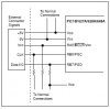
I have built a JDM style serial programmer using an external power supply to power the pic. I have read the datasheet for the 16F628A and to enter LVP I have to pull MCLR and PGM to high. RB7 is hooked to pin 4 & 8 of the serial port. PGM is to pin 3 with a 10k resistor. If I wanted to use HVP could I not pull PGM high and use 13+ volts to MCLR?