Continue to Site

Welcome to our site!

Electro Tech is an online community (with over 170,000 members) who enjoy talking about and building electronic circuits, projects and gadgets. To participate you need to register. Registration is free. Click here to register now.

  • Welcome to our site! Electro Tech is an online community (with over 170,000 members) who enjoy talking about and building electronic circuits, projects and gadgets. To participate you need to register. Registration is free. Click here to register now.

Isis proteus help

Status
Not open for further replies.
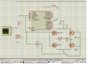
Hi guyz...........i am facing a problem is proteus how can i check the waveform across a resistor or any component using oscilloscope since the scope just has terminals channels A,B,C,D there is no ground it always gives the signal with respect to ground how can i use it to check the signal across a component?
 
differential scope probe would be the standard method.

What kind of common mode voltage rejection are you looking for?
 
this is a sine wave generation by atmega controller check the image i ve connected the scope on the capacitor as the other leg is already ground but in the case of bridge the i want to check the voltage across capacitor only how will i do that?
 

Attachments

  • Untitled.jpg
    Untitled.jpg
    286.9 KB · Views: 1,147
where is the resistor in the circuit ??..............and in the circuit of bridge i want to read voltage aross capacitor not with ground
 
Ian, he is trying to measure the voltage across the capacitor connected to the H-bridge, not the one at the PIC output.

If your scope can be battery powered, quite a lot of them can be these days, then unplug it from the mains and you remove the ground path; the scope will be floating. You can then simply connect your probe across the capacitor. The only other way is with a diff probe.

By the way if you were to implement this in practise you would have big problems with shoot through. The turn-off time of the IGBTs is NOT instant.
 
Ah sorry, I had assumed he was trying a real world measurement.

I'm not familiar with ISIS, it doesn't have a differential probe / voltage probe?

Connect an dual rail, unity gain opamp across the capacitor, the output can then be measured with respect to ground.

A 1:1 transformer would do the job as well, could be put in place of the inductor if you give it a primary inductance equal to that of the inductor.
 
actually friend i want to make a pure sinewave inverter using pwm techinique i have done a part of it i ve made out the reference sine wave from controller and passing it through LC filter i get a pure sine wave i want to use those pulses and increase the output to 220V and about 5A output current means 1KW inverter what should be the next step after making the reference sine wave i was using a full bridge mos circuit for it please guide in detail
 

Attachments

  • Untitled.jpg
    Untitled.jpg
    221.4 KB · Views: 529
you'll need to put it through a transformer with a sufficient turns ratio.

What are you using as a power source?
 
i will use a 12V battery the bridge circuit will take the pwm as gate input and then switch on the pwm and then i have to make the power to 1KW what should i do ?
 
Status
Not open for further replies.

New Articles From Microcontroller Tips

Back
Top