Electro Tech is an online community (with over 170,000 members) who enjoy talking about and building electronic circuits, projects and gadgets. To participate you need to register. Registration is free. Click here to register now.
Welcome to our site! Electro Tech is an online community (with over 170,000 members) who enjoy talking about and building electronic circuits, projects and gadgets. To participate you need to register. Registration is free. Click here to register now.
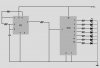
You have pin 1 of the CD4024 shorted to ground.
The resistor from pin 3 of the 555 and pin 1 of the CD4024 is useless and can be replaced by a piece of wire.
A supply bypass capacitor is missing.
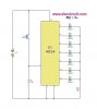
Hmm...okay, that's what I thought. That being so, then there are some false circuits floating around out there...deceiving poor minds like my own! Check it out...
Anyways, cool. That explains the erradic behavior. Thanks!
That circuit is crap! About 75% of circuits posted on the web are put up by noobs who are much better at screwing with html than they are electrical engineers.
First, Since the 4024 is a binary counter, and multiple outputs can be on at the same time, the LEDs connected to the outputs cannot share one common resistor.
Second, the push-button used to generate the clock input needs to be "de-bounced" because if connected as shown, the switch generates "glitches" (multiple spurious rapid closings/openings) which will advance the counter unpredictably.
Third, it needs a bypass capacitor across the power pins on the counter.
btw- I went and looked at about five circuits posted on that site. I found similar deficiencies with almost every one I looked at.
This site uses cookies to help personalise content, tailor your experience and to keep you logged in if you register.
By continuing to use this site, you are consenting to our use of cookies.