Continue to Site

Welcome to our site!

Electro Tech is an online community (with over 170,000 members) who enjoy talking about and building electronic circuits, projects and gadgets. To participate you need to register. Registration is free. Click here to register now.

  • Welcome to our site! Electro Tech is an online community (with over 170,000 members) who enjoy talking about and building electronic circuits, projects and gadgets. To participate you need to register. Registration is free. Click here to register now.

is this battery backup with charging capability ok

Status
Not open for further replies.

nikhil arora

New Member
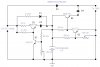
The ckt which i have shown is for giving battery backup to a system which should work continuosly, system req 5V and i have used 12 v battery , now when the light goes, the battery is connected to ckt via diode and when the battery is near to danger level of discharge it should cuttoff itself from the load.
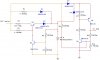
and when the ac power is regain then the battery should charge but little faster,


100 ohm resistor should be changed to 47ohm
 

Attachments

  • battery9v.jpg
    battery9v.jpg
    59.7 KB · Views: 497
I don't understand how it's supposed to work, but maybe if you fix Q4 and/or D4, it will make more sense. Current cannot flow through them as drawn. Is Q4 supposed to be an NPN?
 
q3 and q4 makes circuit to switch off the current when battery voltage falls to critical value med power transitor Q4 is switch on and off by q3.

ur suggestions are very much welcome.
 
nikhil arora said:
q3 and q4 makes circuit to switch off the current when battery voltage falls to critical value med power transitor Q4 is switch on and off by q3.

ur suggestions are very much welcome.
You didn't answer my question: Is Q4 supposed to be an NPN?
 
THIS IS THE NEW CKT WHICH I AM POSTING. NOW THIS WON'T CONFUSE U MUCH.

HERE Q1 IS USED FOR SWITCHING BETWEEN SLOW AND FAST CHARGE.
R2 CAN BE CHANGED AS REQUIRED FOR FAST CHARGING.
 

Attachments

  • battery12vab.jpg
    battery12vab.jpg
    82.7 KB · Views: 435
nikhil arora said:
THIS IS THE NEW CKT WHICH I AM POSTING. NOW THIS WON'T CONFUSE U MUCH.

HERE Q1 IS USED FOR SWITCHING BETWEEN SLOW AND FAST CHARGE.
R2 CAN BE CHANGED AS REQUIRED FOR FAST CHARGING.
You're correct. That is much easier to understand.
It looks good to me. :)
 
now i am through with power supply design
with the help of this forum,
thanks for help.
 
nikhil arora said:
now i am through with power supply design
with the help of this forum,
thanks for help.
I hope this is not for a commercial product. The temperature coefficient of your 12V charger regulator is about 35mV/deg C. This is probably OK in a home environment, where the temperature is controlled, but from 0 to 40 degrees, the voltage will change by about -1.4 volts. I would think this is too big a range for a battery maintenance voltage.
 
Thank you for pointing out this problem in the above ckt.
At present the working condition of this will be at home and offices where temperature will not change much. so we can go ahead.

But when I will upgrade my product i surely add this.
i will remember ur suggestion
thank you once again
electronics god.
 
Status
Not open for further replies.

Latest threads

New Articles From Microcontroller Tips

Back
Top