Electro Tech is an online community (with over 170,000 members) who enjoy talking about and building electronic circuits, projects and gadgets. To participate you need to register. Registration is free. Click here to register now.
Welcome to our site! Electro Tech is an online community (with over 170,000 members) who enjoy talking about and building electronic circuits, projects and gadgets. To participate you need to register. Registration is free. Click here to register now.
I used some advice and decided not to go with the LM324 as a microphone preamp.Is this a little better and simpler?I want the frequency to cover between 500Hz and 3000Hz.Is there a way I can make it variable in this circuit?
I'm pretty sure, this two-transistor preamp much better as 324 amp. for mic. amplifying. 500....3000Hz is a phone quality, this circuit can work over 40kHz!
There are no real frequency limiting components in the circuit, apart from the coupling capacitors - which will limit the low frequency response, but it will still be nice and low.
So he's not calculated it, he's basically 'guessed' it - and I agree with him, it'll work well into the ultrasonic frequencies.
But it's simple, it's cheap, build one and try it!.
what were the factors that told u the frequency range?? i know that analog design is a bit like magic but there is always a good logical reason for everything
from my knowledge i know the following things.
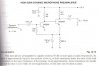
both transistors are in the common emitter configuration and class A
both the output and the input is capacitor coupled
the 150K ohm resistor is producing negative feedback
but what do the 100 microfarad 3V capacitor and the 10 microfarad 16V capacitor do??
Presumably from experience, it's a old tried and tested design, I first saw it in a very old Mullard application note.
what were the factors that told u the frequency range?? i know that analog design is a bit like magic but there is always a good logical reason for everything
from my knowledge i know the following things.
both transistors are in the common emitter configuration and class A
both the output and the input is capacitor coupled
the 150K ohm resistor is producing negative feedback
The 3V capacitor prevents AC negative feedback, by decoupling the emitter to ground. The 16V one is just an HT decoupler, it makes the 12V rail and ground the 'same', as far as AC goes - it's an important component in almost every circuit.
This site uses cookies to help personalise content, tailor your experience and to keep you logged in if you register.
By continuing to use this site, you are consenting to our use of cookies.