Continue to Site

Welcome to our site!

Electro Tech is an online community (with over 170,000 members) who enjoy talking about and building electronic circuits, projects and gadgets. To participate you need to register. Registration is free. Click here to register now.

  • Welcome to our site! Electro Tech is an online community (with over 170,000 members) who enjoy talking about and building electronic circuits, projects and gadgets. To participate you need to register. Registration is free. Click here to register now.

Is this a good CMOS Pulse

Status
Not open for further replies.
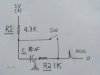
what is the differential.R1 / C /R2 formula for pulse duration . I have heard the question asked about a single pulse switch..... this worked for me on a cmos circuit. this its in a CMOS circuit, 5V
someone is going to say use a 555, the formula should be the same........? oh..... please us the capacitance as UF
 

Attachments

  • HPIM1675.JPG
    HPIM1675.JPG
    90.6 KB · Views: 162
Last edited:
Should work.
Problems:
1) C1 needs to charge up to about 5 volts before the switch is closed. You must allow C1 to charge up.
2) WhenS1 is open the output is 0 volts (good)
....When S1 closes the output jumps up to the voltage on C1 (hopefully 5V)
....The voltage heads down to a little less than 1 volt. The 4.7k pulling up and the 1k pulling down make a voltage divider. (might be a problem)
.....When the switch opens the voltage drops to 0 volts.
3) Your time constant (RC) is strange because the voltage is not discharging to 0 volts but to 0.8Volts. The math is harder.
 
Status
Not open for further replies.

Latest threads

Back
Top