Continue to Site

Welcome to our site!

Electro Tech is an online community (with over 170,000 members) who enjoy talking about and building electronic circuits, projects and gadgets. To participate you need to register. Registration is free. Click here to register now.

  • Welcome to our site! Electro Tech is an online community (with over 170,000 members) who enjoy talking about and building electronic circuits, projects and gadgets. To participate you need to register. Registration is free. Click here to register now.

Is it time for a new Scope?

Status
Not open for further replies.

SPDCHK

Member
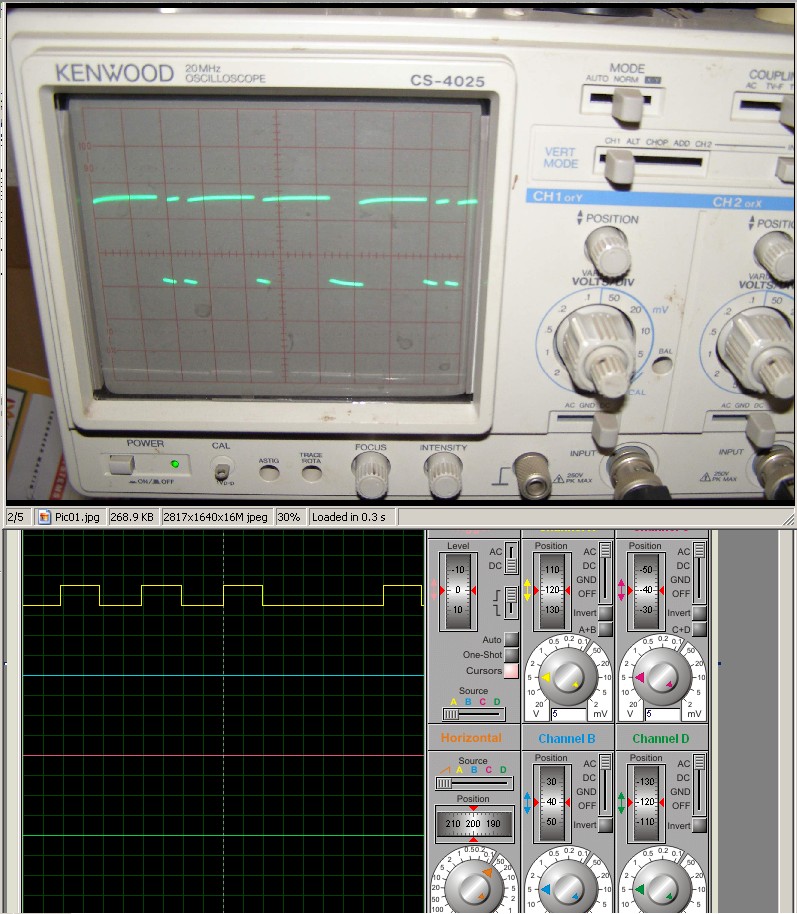
I loaded the following code in my 12F675 PIC and tested it with my Kenwood Oscilloscope. The results was not what I expected. I then loaded the file into my simulator (Proteus) and there the results came out as what I expected.

Now the question is: Do I need a new scope? Which of these two pieces of test equipment should I trust? I'd rather believe the scope vs. computer simulated software.

Can someone with a newer scope perhaps test the code?

Thanks.

scopediff-jpg.29986
 

Attachments

  • ScopeDiff.jpg
    ScopeDiff.jpg
    190.8 KB · Views: 332
Last edited:
have you tried the scope with other known sources to eliminate the possibility that it is showing you what is really occurring?
 
Have you correctly adjusted the scope's probe?

Test your scope with its internal calibration signal and with an external source.

Looking at your first picture though, it seems to be working.
 
Now the question is: Do I need a new scope? Which of these two pieces of test equipment should I trust? I'd rather believe the scope vs. computer simulated software.

Can someone with a newer scope perhaps test the code?
Thanks.

Hi SPD,
I like simulators and I believe they have a place in testing BUT I would trust real hardware over a simulation.:)

I prefer 'raw' data over processed data anytime.
 
Have you correctly adjusted the scope's probe?

Test your scope with its internal calibration signal and with an external source.

Looking at your first picture though, it seems to be working.

Yes, I tested both channels to the internal calibration signal. Even to 50Hz.

I've written the code such that It should be on/off with 100us intervals, but from the scope indication, the periods are no where near the same ??? :confused:
 
The scope looks like it is probably working fine. I am assuming the display is stable as pictured indicating no triggering / holdoff problems.

I can't think of any failure mode of an analog scope that would muck with timing between pulses... well, not without distorting the display but that isn't happening.

You must be a software guy if you're blaming the hardware. :D J/K

Good luck in troubleshooting!

Michael

:D Yes, I suppose I can be called a software guy, but in this case I'd rather believe the hardware. It just seems odd that the On/Off periods don't display the same on the scope. :confused:
 
That is weird...

But if the trace is stable on the scope, then WYSIWYG I am pretty sure.

The scope has a timing circuit that controls the horizontal sweep. If there is a problem with it, the trace will look funny (varying intensity across the sweep). If there is a problem with triggering or holdoff I would think it'd affect all signals in funny ways.

So... maybe it is some weird timing issue with the interrupts... or maybe the MCU isn't configured the way it needs to be (ie, the way the simulation assumes it is) ... ??

Michael
 
Your scope probe appears to be under-compensated, but other than that, the waveform looks to be a proper display of what the circuit is doing.
 
The scope looks like it is probably working fine. I am assuming the display is stable as pictured indicating no triggering / holdoff problems.

I can't think of any failure mode of an analog scope that would muck with timing between pulses... well, not without distorting the display but that isn't happening.

You must be a software guy if you're blaming the hardware. :D J/K

Good luck in troubleshooting!

Michael

FEEDBACK

I added to my code a start pulse of 50µs and assigned the output to one of the unused I/O pins. I connected the scope’s external trigger probe to this I/O pin, and continued using the channel A probe to measure the databus, and voila, my old scope is still as good as the day I bought it.

Thanks for all the help you guys.
 
Status
Not open for further replies.

New Articles From Microcontroller Tips

Back
Top