G'day all,
I'm hoping to repair an irrigation controller. It energises the solenoid valve for one second only, and displays a flashing 24V symbol indicating a wiring or solenoid short.
However the wiring is definitely fine, and a new valve & solenoid behaves the same.
Directly connecting the solenoid to the 24V AC supply opens the valve and it stays open as long as it's powered.
It's an Australian Pope DigiMax 8, which is probably around 10-20 years old, and Pope no longer can provide any guidance (including the circuit diagram).
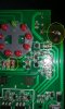
It appears to have had some serious heat at one corner of the PCB, most likely the medium sized resistor there (1-2W at a guess).
I took the board into a local electronics supplier (Jaycar) and while the resistor looked a bit cooked, they pointed out a little zener diode with a bit of browning around it, that they thought to be a more likely culprit (see the attached macro photo).
They don't stock SMDs and suggested **broken link removed**. Looking at their catalog, I see thousands, so I've been trying to figure out how to spec it.
I'm reluctant to write this gadget off as its replacement is probably a couple hundred bucks worth, especially if I can fix it for a few cents")
Any suggestions? I can take more photos if that's helpful.
Cheers, David
I'm hoping to repair an irrigation controller. It energises the solenoid valve for one second only, and displays a flashing 24V symbol indicating a wiring or solenoid short.
However the wiring is definitely fine, and a new valve & solenoid behaves the same.
Directly connecting the solenoid to the 24V AC supply opens the valve and it stays open as long as it's powered.
It's an Australian Pope DigiMax 8, which is probably around 10-20 years old, and Pope no longer can provide any guidance (including the circuit diagram).
It appears to have had some serious heat at one corner of the PCB, most likely the medium sized resistor there (1-2W at a guess).
I took the board into a local electronics supplier (Jaycar) and while the resistor looked a bit cooked, they pointed out a little zener diode with a bit of browning around it, that they thought to be a more likely culprit (see the attached macro photo).
They don't stock SMDs and suggested **broken link removed**. Looking at their catalog, I see thousands, so I've been trying to figure out how to spec it.
I'm reluctant to write this gadget off as its replacement is probably a couple hundred bucks worth, especially if I can fix it for a few cents
Any suggestions? I can take more photos if that's helpful.
Cheers, David