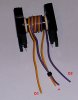
Please view the attachment of SMPS circuit which was modified by me to fulfill my requirements. I made three PCB's of the above SMPS (Output about 220V/1.5A DC). The problem is that one PCB is working fine and delivering my desired voltage & current (i.e. 220V/1.5A DC). But in the remaining two PCB's, power MOSFET (IRFP064) gets burnt within 2-3 minutes.
My question is that when the three PCB's are identical, so why one board is working satisfactorily & other two boards are not functioning properly? I thoroughly checked everything in all PCB's but remained unsuccessful. Hence please help in this respect.
Further another question is that can I use power transistors (e.g TIP35) despite using MOSFET's? By providing sufficient driving to the transistors?
Note: The IC is TL494
Best regards