Continue to Site

Welcome to our site!

Electro Tech is an online community (with over 170,000 members) who enjoy talking about and building electronic circuits, projects and gadgets. To participate you need to register. Registration is free. Click here to register now.

  • Welcome to our site! Electro Tech is an online community (with over 170,000 members) who enjoy talking about and building electronic circuits, projects and gadgets. To participate you need to register. Registration is free. Click here to register now.

IRF511 Fet problem contest

Status
Not open for further replies.

breadboardguy

New Member
I am having a contest in a week and i am making the final version of my line following robot (my prototype worked out well) ...

BUT...

I am getting back to the joys of debugging obvious problems and then running crazy.

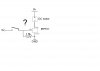
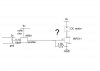
I need to command the robot with two Fet IRF511, but for some reason that i dont know, Dosnt worksss ... it was working in the prototype tough............

I have a schematic just here ;

Help! (whats wrong????)
 

Attachments

  • IRF511 problem.JPG
    IRF511 problem.JPG
    29.6 KB · Views: 624
There's nothing wrong with the basic schematic (aside from the missing flyback diode), but 5 volts is WAY too low a voltage to be feeding that mosfet. According to the data sheet at 5 volts you're going to get a maximum current of 1amp. To get it's rated ~5amp current you'll need a gate voltage minimum of 7 volts, to get really low RDS on value you'll probably need even more than that. If your motor pulses high currents when it starts (like all motors do) you'll need 10+ volts of gate drive.
You'll need to add a simple transistor voltage level switcher to the gate so the 5V can drive the transistor to provide the 9V rail to the gate since that's the highest voltage you have to work with it'll have to do.

I can post a transistor level shift I made but my schematic drawing is pretty horrible cause I use a simulator and have no sense of organization in it =) Or other users might be able to post simple a simple schematic to bootstrap the voltage for you. If you don't get any responce for a circuit to do that I'll post one later on today.
 
Last edited:
Wow, fast answer!

I think that i can make the voltage of 9 volt with a pair of small signal transistor (npn and pnp)

But i would like to avoid that, isnt there TTL voltage FET out there?
 
Sure. But even those will benefit from higher gate drive, and they typically have higher gate capacitance so they can't be switched as fast. If you're dealing with a mosfet you have to deal with these issues as well, it's simply the way the devices work there is no way to work around it you can at BEST mitigate one problem at the expensive of increasing another. That's why proper drive circuits especially on power mosfets are so important. In your application depending on the motor and actual current draws the gate drive voltage alone would cause the circuit to either work extremely well or burst into flames.
 
... I think that i am having a bisexual pnp small signal transistor here...

Either i put 5 volts or gnd, the pnp switchs on and supplys 9 v on the fet, wich turns the motor on......

Is this normal?


Edit:

If i put both on it shorcuts(duh!) and if i put nothing, it shuts off...
 

Attachments

  • IRF511 problem.JPG
    IRF511 problem.JPG
    39.3 KB · Views: 647
Last edited:
You won't get more than 5 volts out of that circuit, it'll act as a voltage follower. You need both a PNP and NPN transistor to do rail to rail voltage adjustment.
 
I dont know, but i have tryed it on a breadboard and it very strangely works...

Why? 9 volts is generated by that strange pnp and the fet turns on ( its a fact) wich makes the motor run....

Could this be due to some interference of what? Really strange.
 
Are you using an oriental 2SA684 PNP transistor? Then you connected its collector and emitter backwards.

Connect the PNP transistor with its emitter at +9V and its collector at the gate pin of the Mosfet.
It needs a series base resistor then it will apply about +8.9V to the gate of the Mosfet when its base resistor is 0V and it will apply +8.8V (the Mosfet will still be turned on) when its base resistor is +5V. Its base resistor must be +9V for it to turn off.
 
Last edited:
I am not shure to get what you mean, whats a "serie base resistor"?

Anyway, i have made a voltage amplifier with two combo of small signal transistor.

Works fine, thanks for the help.

(It must be one of the fastest answering forum on the internet:) )

I have connected the pnp 2sa684 correctly ( e c b from the front).
 
Last edited:
You already have a series base resistor.

The emitter of a PNP transistor must be connected to the most positive voltage. Yours is connected backwards. Look at your schematic where the collector is wrongly connected to +9v and the emitter wrongly connects to the load.
 
Anyway, thank for your help , i've just completed my line following robot and it works much better then the prototype.

Yay!
 
Status
Not open for further replies.

Latest threads

New Articles From Microcontroller Tips

Back
Top