Electro Tech is an online community (with over 170,000 members) who enjoy talking about and building electronic circuits, projects and gadgets. To participate you need to register. Registration is free. Click here to register now.
Welcome to our site! Electro Tech is an online community (with over 170,000 members) who enjoy talking about and building electronic circuits, projects and gadgets. To participate you need to register. Registration is free. Click here to register now.
Hey guys , I've recently purchased some IRF6609's
They come in DirectFet packages , Which are Leadless flat rectangles..
My question is , How would i solder them onto the board? Solder paste?
An oven?
Any recomendations?
Hey guys , I've recently purchased some IRF6609's
They come in DirectFet packages , Which are Leadless flat rectangles..
My question is , How would i solder them onto the board? Solder paste?
An oven?
Any recomendations?
As far as I'm aware (and I don't have equipment to do them) you need to simultaneously heat both sides of the board to an accurately controlled temperature, presumably you use solder paste? (or pre-tin both board and component).
I have a friend who's got all the gear, he replaces multi-hundred pin BGA (Ball Gate Array) in digital satellite receivers.
My recommendation would be to pick some easier to handle FET's!.
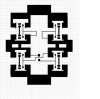
I am happy to report that the toner transfer method worked beautifully..
I just laser printed the above pattern on a piece of magazine paper and ironed it to the circuit board.. then soaked the board in water.. then ecthed the board.. then tinned the board with solder..
now the bad news.. when i get done soldering one transistor on and test it , and go on to the next one, somewhere along the line the previous tansistor desolders itself ..sigh , i might have to make them farther apart
:lol: It is something I had to do all day when I worked as a prototype tech................If you solder one part on and the clamp a heat-sink to the board between the two peaces you will have no trouble with temperature creeping along the tracks.
If you do still have trouble then your iron is too hot, make sure you are using LMP paste (Low Melting Point). And check your iron is set correctly for SMD's, you may also be holding the iron on the joint for too long........
I could go on for days But I hope you get the idea...........
I have been were you are now, I was a development tech, as I said and had to make many prototype boards by hand.............. I would also recommend you buy some cheap SMD resistor packs and practise soldering them.......it is totaly differant to through plated soldering..
It is something I had to do all day when I worked as a prototype tech................If you solder one part on and the clamp a heat-sink to the board between the two peaces you will have no trouble with temperature creeping along the tracks.
It's not hard to understand. You form a heatsink in order to disipate the heat away from the commponents that you have already soldered to the board........................
It's not hard to understand. You form a heatsink in order to disipate the heat away from the commponents that you have already soldered to the board........................
i just ran a test , with the generator hooked through half the board , and got a tad over 700mA , but one transistor was getting hot , so i assume the one was'nt soldered perfectly correct .. i tell ya i have never had such a hard time soldering anything before this..
what i found worked best was to put a tiny bit of solder on the transistor , then put it in place , then heat the back..
maybe if i can find some low temp solder , locally, things will improve :roll:
on the bright side 700mA was the most i've ever got from the half wave rectified power coming from the generator..
I am going to give up on the directFets..
i ordered some IRF3703's that come in a TO220 package..
the IRF3703 has a RDS(on) (on resistance) of just 2.8 mOhms ..
a Vgs of 20V
a max current capacity of 210 Amps.. :lol: depending on the junction temperature
i cant wait till they get here.. 8)
I am going to give up on the directFets..
i ordered some IRF3703's that come in a TO220 package..
the IRF3703 has a RDS(on) (on resistance) of just 2.8 mOhms ..
a Vgs of 20V
a max current capacity of 210 Amps.. :lol: depending on the junction temperature
i cant wait till they get here.. 8)
That 2.8mOhms does NOT include the leads.
I don't think '220 leads are rated to carry 210 amps! (continuously anyways)
These will have GOBS of junction capacitance so if you are going to switch them fast, it will be very tough (many amps of transient gate current needed)
They sound nice though.. how much did they rip you off for?
They were $33 plus shipping for 10..from digikey..
you're right !! note 6 states "Package limitation current is 75A"
bastards.. :lol: https://www.electro-tech-online.com/custompdfs/2005/09/irf3703.pdf
oh well :lol: , i wont be getting anywhere near the limit ..
btw this is for my diodeless rectifier.. 8) :lol:
This site uses cookies to help personalise content, tailor your experience and to keep you logged in if you register.
By continuing to use this site, you are consenting to our use of cookies.

 ..sigh , i might have to make them farther apart