Continue to Site

Welcome to our site!

Electro Tech is an online community (with over 170,000 members) who enjoy talking about and building electronic circuits, projects and gadgets. To participate you need to register. Registration is free. Click here to register now.

  • Welcome to our site! Electro Tech is an online community (with over 170,000 members) who enjoy talking about and building electronic circuits, projects and gadgets. To participate you need to register. Registration is free. Click here to register now.

IR2110 H-Bridge Inverter for Induction Heater

Status
Not open for further replies.

mohiuddinhimel

New Member
Hi,

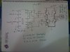
I was designing a High Power High frequency Induction Heater inverter. I choose H-bridge configuration for the inverter
and IR2110 gate drivers to drive the bridge. As the IR2110 is a half-bridge driver i'll use two of them to drive the both sides.
I've done a rough circuit(just drawing). As i dont know much about power electronics i wonder if there is any mistake.

i am looking for advice, recommendation, and any kind of error that should be fixed in my circuit.

Also i've some questions:

1) what is the use of C3 n how i'll calculate the value?
2) Exactly which back EMF protection Diode should i use as D' ?
3) Do i need to use an opto-isolator for high side nMosfets?

The intended frequency is 150KHz and the Mosfet's are N-type.
 

Attachments

  • H-bridge.jpg
    H-bridge.jpg
    2.6 MB · Views: 10,093
1- To answer #1. C1, C2 and C3 are on the wrong pins in your drawing.
C3 when on pin 6 is the boost capacitor. It gets charged to almost 2x the logic supply voltage and "floats" on top of the source voltage so that the gate voltage can be 10 volts above the source voltage to turn on the high side FET. A rule of thumb is that it be at least 10x the total gate capacitance of the FET. I would use the .1Ufd. shown in the data sheet even if it is much more.
2-Depends on the current you need. At 180 volts you will probably need to use a ultra-fast recovery diode.
3-Your 180 volt supply should be isolated from the line. So no opto required.
You may have a problem with shoot thru from the high side through the low side. There are drivers that will protect from this or you can "play" with the logic to eliminate it.
 
what Mofets are u Using ???
Still haven't confirmed yet. As i have to test performances of different types of Fets. Its just a initial design.

And for the power source i'll use a variac then rectify the signal and then filter it by a capacitor bank of 3600uf 500volt
 
1- To answer #1. C1, C2 and C3 are on the wrong pins in your drawing.
C3 when on pin 6 is the boost capacitor. It gets charged to almost 2x the logic supply voltage and "floats" on top of the source voltage so that the gate voltage can be 10 volts above the source voltage to turn on the high side FET. A rule of thumb is that it be at least 10x the total gate capacitance of the FET. I would use the .1Ufd. shown in the data sheet even if it is much more.
2-Depends on the current you need. At 180 volts you will probably need to use a ultra-fast recovery diode.
3-Your 180 volt supply should be isolated from the line. So no opto required.
You may have a problem with shoot thru from the high side through the low side. There are drivers that will protect from this or you can "play" with the logic to eliminate it.

Thnax for the feedback! btw there is another cap between the Vdd and Vss of the chip in the datasheet of IR2110. Is it mandatory for my circuit??
 
Wait.... The variac will not provide isolation from the AC line. Everything will be dangerous.
 
Status
Not open for further replies.

New Articles From Microcontroller Tips

Back
Top