Ayne
New Member
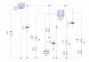
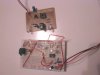
Below is the circuit I have assembled.
I have done these checks.
1. I see my IR LEDs in Mobile camera... It was ON, when i Pull Down RST Pin Down to ground LED Became OFF. (It means 555 working fine)
2. I check the frequency of 555 on oscilloscope and set it to 38.05KHz.
My IR transmiting LEDs and receiver on the same PCB.
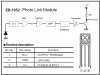
I put a mirror infront of Transmitter. IR waves are reflected back but IR receiver Data PIN is still to High. It is not going to LOW.
But when I Press My TV's(SONY) remote button infront of IR receiver The date PIN oscillate between HIGH and LOW.... (I think it is right condition cuz Remote sending codes High and LOW)
What can be the Problem why Receiver not detecting wave created by my transmitter.
I have done these checks.
1. I see my IR LEDs in Mobile camera... It was ON, when i Pull Down RST Pin Down to ground LED Became OFF. (It means 555 working fine)
2. I check the frequency of 555 on oscilloscope and set it to 38.05KHz.
My IR transmiting LEDs and receiver on the same PCB.
I put a mirror infront of Transmitter. IR waves are reflected back but IR receiver Data PIN is still to High. It is not going to LOW.
But when I Press My TV's(SONY) remote button infront of IR receiver The date PIN oscillate between HIGH and LOW.... (I think it is right condition cuz Remote sending codes High and LOW)
What can be the Problem why Receiver not detecting wave created by my transmitter.