Continue to Site

Welcome to our site!

Electro Tech is an online community (with over 170,000 members) who enjoy talking about and building electronic circuits, projects and gadgets. To participate you need to register. Registration is free. Click here to register now.

  • Welcome to our site! Electro Tech is an online community (with over 170,000 members) who enjoy talking about and building electronic circuits, projects and gadgets. To participate you need to register. Registration is free. Click here to register now.

IR Reciever Module Pin Out??

Status
Not open for further replies.

Peter_wadley

New Member
Hey,

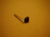
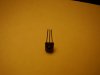
I finally went out and bought the IR reciever module again.. i still do not know the correct way to wire it becuase I dont have the pinout or datasheet.

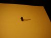
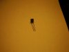
The pictures are attached below, I took shots of many angles.

From looking at the module head on (with the black bulb facing you)

what should the pin out be left to right?

Is there ANY way to tell if the pinout is correct?

Will the data line be 0v or 5v when it is wired correctly with no IR being emitted on it?

Thanks for any help!
Peter Wadley

Ps. I already know some of the pictures are blurry no need to tell me.
 

Attachments

  • P1050004.JPG
    P1050004.JPG
    230.2 KB · Views: 494
  • P1050006.JPG
    P1050006.JPG
    226.8 KB · Views: 495
  • P1050007.JPG
    P1050007.JPG
    163.2 KB · Views: 357
  • P1050008.JPG
    P1050008.JPG
    176.5 KB · Views: 358
  • P1050009.JPG
    P1050009.JPG
    231 KB · Views: 297
  • P1050010.JPG
    P1050010.JPG
    202.9 KB · Views: 337
The problem with these IR receivers is that unless you know the part number you will not know which remote control carrier frequency it is designed to work with.

For example, the Vishay TSOP48xx series datasheet shows seven variants:

http://pdf1.alldatasheet.com/datasheet-pdf/view/26654/VISAY/TSOP4830.html

If you are lucky, it may be a 36kHz type which works with Phillips remote controls. (They use the RC5 standard protocol which can be decoded with a PIC micro.
see: http://users.pandora.be/davshomepage/rc5.htm
 
Throw it away and buy a real IR receiver from a real electronic parts distributor. Get its datasheet first.
 
How expensive is your part? I did an AVR project last december with an unknown and it worked fine. Go to Nigel's website and wire it up just like he shows. Don't cut corners, you need the cap and resistor. The output should be HIGH with know signal, drops LOW when it detects. The center frequency is a guideline for best performance, anything close will work to some degree. I used the remote from VCR and oscilloscope to verify it was working. Didn't know the frequency of the module or VCR remote, and all was well.
 
audioguru said:
Throw it away and buy a real IR receiver from a real electronic parts distributor. Get its datasheet first.

Damn it, your so unbelievably right on the mark on this one :mad:

What a damn waste of money..

2 x $4 = Could have been lunch money :mad:


If, when you look straight on to it (bulb facing you), the right pin is 1 middle is 2 and left is 3..

I hooked 1 to 5v.. 2 to GND and 3 to a 1000:eek:hm: resistor to an LED going to GND..

The LED stays on until I point my TV controller at it.. which makes it blink off and on..

I think this thing is damn junk.

Please let me know if this will work as in Nigels tutorials

The one I have now isnt even doing the above anymore .. i think i most likely have burnt it out from trying the power supply wiring on every pin :p

from a real electronic parts distributor

care to name one please? Sayal is pretty much crap as you know... I went to ACTIVE in mississauga.. it was alright.. except for the fact that they are selling a pic16F877a for 20 bucks!!! RIP OFF.

The source doesnt sell IR reciever, I cant find this damn IC anywhere except sayal!!!

Its 4 bucks or one harvey
 
Peter_wadley said:
I hooked 1 to 5v.. 2 to GND and 3 to a 1000:eek:hm: resistor to an LED going to GND..

The LED stays on until I point my TV controller at it.. which makes it blink off and on..

I think this thing is damn junk.

Sounds like it's working perfectly?.

Although I wouldn't suggest connecting the LED to ground, but from +ve to the output, so it blinks ON as it receives the pulses.

The source doesnt sell IR reciever, I cant find this damn IC anywhere except sayal!!!

Simply get one out of any old TV, VCR, stereo etc. - make sure you check which pin is which before you remove it.
 
When I order online (or by phone) at Newark or at Digikey before 8:00PM then it is delivered to me the next morning.

Sayal has good prices on some things and Active is there when I need someting in a hurry.

The Source sells cell phones and consumer products at full list price. They might have some old electronic parts leftovers from RadioShack. I have never bought anything from The Source.
 
Nigel Goodwin said:
Sounds like it's working perfectly?.

Although I wouldn't suggest connecting the LED to ground, but from +ve to the output, so it blinks ON as it receives the pulses.


Simply get one out of any old TV, VCR, stereo etc. - make sure you check which pin is which before you remove it.

Hey there,

I just received 20 of these:

**broken link removed**

When I hook it up as it says in the datasheet the output sit at 4.54V.. when i shine IR light (continuously) on it its output goes to ground..

Is this how it should be working??

Right now im trying to configure a 555 timer to blink the IR LED @ 38khz... anyone know what size caps and resistors i should use?

Thanks and I will try your tutorial with these, Nigel.
 
The datasheet for every 555 has a formula to calculate the capacitor and resistors to set the frequency.
 
audioguru said:
The datasheet for every 555 has a formula to calculate the capacitor and resistors to set the frequency.

Yes I just realized that lol

My main goal is to use the IR to toggle a PIC output on and off..

Is it possible to make the controller with the 555 or must I use another microcontroller? I would rather save the money since its such a trivial task.

Could I just make the controller send the 38khz carrier signal without modulating it?

The receiver practically blocks out all non-IR light and the circuit is in the garage - which is very dim.

Thanks
 
Do you have capacitors across the PIC power pins and one for the IR module? These are important, and prevents the false triggering.
 
HarveyH42 said:
Do you have capacitors across the PIC power pins and one for the IR module? These are important, and prevents the false triggering.

Yes I do have 2 bypass caps on the circuit

Could you recommend what the best sized caps would be?

You also need the PIC to detect it's receiving the correct digital data, and NOT just any random occurance that makes the output go low.

Yes I have been trying to check out your tutorial page but it hasnt been loading today.
 
Forescent lights can cause false triggering on IR modules if there's not method to detect valid data.
 
Peter_wadley said:
Yep, I just shone a floro on it and it activated

Luckily there normally is no floro present :D

But it will trigger from any random occurance which passes through the IR receiver, this is why you require digital coding on the data stream, so the PIC can determine if it's a valid signal or not.
 
Status
Not open for further replies.

New Articles From Microcontroller Tips

Back
Top