Electro Tech is an online community (with over 170,000 members) who enjoy talking about and building electronic circuits, projects and gadgets. To participate you need to register. Registration is free. Click here to register now.
Welcome to our site! Electro Tech is an online community (with over 170,000 members) who enjoy talking about and building electronic circuits, projects and gadgets. To participate you need to register. Registration is free. Click here to register now.
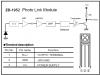
i have a infrared receiver with 3 pins coming out of it,if im looking at the receiver lense where do the pins go ,(the left pin,middle,and right)
any help would be great.....
one of the pins is ground, one is +V (probably 5V) and the other is the signal. ground should be quite obvious, maybe even connected to the metal case. If you can see the circuit board, +V should be fairly easy to discern.
best way, though, is as johnsmith said - get the part number and find the datasheet.
thanks i set it up , i used a 5v regulator on pin 3 and i grounded pin 2 but pin 1 is showing about 1.19 volts without transmitter and about 1.28 with the transmitter shouldnt it be oV without transmitter
Its output should go low if it receives an IR beam that is modulated with its carrier frequency, and go high in the dark. Its output doesn't change as much as it should so it must have daylight or a compact fluorescent bulb shining on it.
i connected pin 1 (output) to pin 3 (+V) with a LED,and i got the tv remote and pressed a button and the LED started flashing,is that the way it is supposed to work???
i connected pin 1 (output) to pin 3 (+V) with a LED,and i got the tv remote and pressed a button and the LED started flashing,is that the way it is supposed to work???
i tried making a transmitter with a standard collector emitter transmitter LED but im getting zero results with it, the tv remote is working excellent with over 20 meter rang and it flashes due to the tv remote,is there a simple way to set it up so it stays on rather than flashing.
You need to modulate the LED with 38KHz or so - bear in mind though that the receiver is designed for data pulses, and NOT for continuous carrier - so range will probably be considerably reduced.
Look at the datasheet for a 555. It has a chart with resistors and the timing capacitor values and frequencies. It also has a formula for you to accurately calculate their values.
The IR receiver you got doesn't have its frequency specified, does it?
Look at the datasheet for a 555. It has a chart with resistors and the timing capacitor values and frequencies. It also has a formula for you to accurately calculate their values.
The IR receiver you got doesn't have its frequency specified, does it?
No it is not! The datasheet shows 36kHz ones, 38kHz ones and 40kHz ones. Jaycar ripped you off since they are all mixed up.
It will be difficult to find out the exact frequency. Adjust the frequency of the transmitter then measure the range. Adjust the frequency of the transmitter again then measure the range again.
This site uses cookies to help personalise content, tailor your experience and to keep you logged in if you register.
By continuing to use this site, you are consenting to our use of cookies.