Continue to Site

Welcome to our site!

Electro Tech is an online community (with over 170,000 members) who enjoy talking about and building electronic circuits, projects and gadgets. To participate you need to register. Registration is free. Click here to register now.

  • Welcome to our site! Electro Tech is an online community (with over 170,000 members) who enjoy talking about and building electronic circuits, projects and gadgets. To participate you need to register. Registration is free. Click here to register now.

IR gate-help

Status
Not open for further replies.

indika perera

New Member
Hi..all..:)i'm a learner of electronics..so not having good knowledge of electronics..these days i'm trying to make IR gate
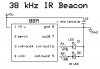
as a security gate..so i used this circuit..
103-20080108065816170.gif

At the beginning this circuit is not worked..then i was able to work receiver part..
but i 'm unable to use that oscillator part work..i have changed that values of capacitors as desire..some time i have seen that IR receiver response to the emitter..but it works for few centimeters..Another thing is i put additional ele.capacitor between output and ground of receiver sensor (before that output LED blinks only once i press TV remote)..it worked to me i don't know how it's happen:confused:..that means when i press TV remote in front of IR sensor that output LED of sensor get off..
so i need your guidance to implement this..what i want from you is..
can anybody tell me that

(1) how to make more powerful IR emitter like TV remote so that what IC should i buy for that..

(2)are there any Remote control IC for use for single button(that means single channel) to operate this kind of barrier circuit..

I'm really glad if anyone help me to make this small circuit..
I'm waiting response from you..

Thank you.......
 
IR transmission and reception is pretty well limited in its distance due to several factors, not the least of which is ambient light. The changers we use for TV are highly coded... first in their frequency of operation, and in the complex order of their instruction pulses.

As to the circuit you have shown, it would appear the author may have intended his circuit to be used as a proximity detector, which means the IR reciever detects light transmitted by the transmitter reflecting off an object in close proximity.

If you haven't done too much tinkering, you might be able to test this theory by adjusting the modules as shown on the circuit, then placing a white card or piece of paper a couple of cm ahead of the sensor. Reflected light should activate the circuit. Also, you should make every attempt to shield the recievers from extra light, expecially fluorescent.

I'm sure there are others who will give you their opinions on the matter.

Good luck.
 
thx..for reply...AllVoll..He tells that this can be used for Ir beam barrier and also for proximity detector..i don't know much more different of that..that is be' of my lack of knowledge..He..He..i thought both beam barrier and proximity detector stick to whether the rays having obstruction or not..
he mentions that the oscillator set for 38KHz so i hve gone through Ne555 data sheet calculations and follow there equations..but i had few doubt of checking those..

thx..indika
 
Last edited:
Okay... beam barrier means the IR beam is on continuously, and the reciever is always seeing the transmitter. If something passes between the two, it breaks the beam and causes the circuit to respond.

In reflection, the transmitter is always on, but there is no response until the receiver sees the transmitted light via reflection.

The easy was to tell if your transmitter module is working is to use a digital camera that has a LCD screen for viewing. Just point the camera at the IR diode and you can see it glowing. Don't be like the fellow who came into Radio Shack one day screaming about the cheap Chinese products. He threw 10 IR diodes down and demanded a refund because he could plainly see they weren't working.

But I digress.

First, get your transmitter working. The rest should then be a snap, whichever way you decide to go.
 
You apparently edited while I was responding. I didn't see the frequency thing.

The 555 is a marvelous little chip, but it is not really noted for its accuracy either on long counts, or for high frequencies. For 38MHz, I would rather use a 74AC14, one cap and a pot, and nail the frequency dead on. But for your purposes, the 555 is perfectly okay for right now.
 
Ok..Allvol..i'll try to check with digital camera..but i think IR emitter is working..the LED is definitely working it can see even from my eyes..be' it lighted little red spot..the only problem is even if i solve that emitter problem..i need to use it for long distance..i don't know how many distance it can reach..even it i use another transistor to increase the output of the IC..i'm looking at least a TV remote control's distance..do u know such IC with easy circuit..plz tell me..
 
actually..i'm from asian region country(NOT CHINA..He..He..)..so here is a problem of getting good quality items..but i'm trying my best to find those.. most of the time i got good ones..
 
As I said to start, IR is difficult to work with at long distances. I have tried several circuits trying to span a 14 foot gap, but nothing reliable yet.

In fact, I have better results at a distance with IR detection of body heat. I have a PIR that can pick up cats walking at 10 feet, and humans to 20 or so.

Good luck. Let me know if you find something.
 
Yes..of couse..it is difficult to get better result as i thought... before i tried to do it..i selected this kind of circuit because of it is simple..PIR circuits needs much more effort...and few more parts..apart from that i wanted to make this as barrier..not as a proximity detector....anyway thx lot for your ideas..i'll put here if i got good one...
best regard..
<indika>
 
if you can make a beam of IR then you can get long distance, may be you will have to use small lense to do it.

if you are trying to use very long distance as a beam barrier, i sugest you to use cheap laser transmitter and a photo transistor can respond to its intensity. you can find laser pointer in local market that can trvel miles, so you even can use many mirrors on its way to make it reflect and travel back to the point of transmitter thus both receiver and transmitter can be nearby.

i didnt try such experiemnt yet with lasers, but i am sure it will work in good way, about receivers for laser there may be good options, if you can search on net.

if your application require invisible ray only then IR is the option you have.
 
So..thx for ur idea...yes..i hope leser is good for long distance...but i need invisible thing and i need only less than 20 feet distance..i realize i can use damaged(key pad) TV remote control for get that chip to make long range IR beam..but i wanted to make this in decent manner..that means using my own circuit...
and another mess i got is i just wanted to know is it possible to use IR LED for long time..because we use TV remote for short period..i guess otherwise it will burn out..plz ..explain..anyone..
 
as i told you, why dont you try to make a beam of IR? as you find in small torch lights, keep the IR diode on the centre instead of the bulb and try. it may give you a straight beam that can travel some far. ie you are directing the emmission to one direction.

about TV remote i dont think thre will be a problem in using it continuosly. also on the diagram you posted try to use a propper current limiting resistor to the diode looking at the data sheet to operate it to maximum efficiency.

try to search for some ready made IR transmitter modules, there are some good ones i remember. also IR diodes even can work with just direct DC but the idea of madulating is to minimize interference at the receiver end.
 
ok.mate..for what purpose to make IR beam..sorry..i can't understand what u are telling..u means that i can make IR beam as same as torch light beam..but it sense that no need to oscillate the beam..but i guess i have to oscillate the beam to receive via IR sensor...(on receiver module).ok i'll folow through some readymade modules...

Thx..
 
Read the datasheet for the IR receiver IC.
It has AGC that reduces its gain when it detects continuous 38kHz IR which is interference caused by compact fluorescent light bulbs (and by your transmitter). The datasheet shows that the 38kHz must be modulated in bursts at a certain rate like a TV remote does. Use a second 555 to modulate the 38kHz 555 then the receiver's gain will be at maximum.

The current pulses in your IR LEDs is only about 39mA. The current pulses in the IR LEDs of a TV remote is about 1A. The 555 can supply only 100mA with its supply as low as 5V.

Your 5V regulator needs an input capacitor and an output capacitor. The 555 also needs a supply bypass capacitor and the IR receiver needs a supply RC filter that is shown in its datasheet.
The transistor will blow up from the high voltage flyback spike from the relay coil without a reversed protection diode across the coil.
 
Status
Not open for further replies.

Latest threads

New Articles From Microcontroller Tips

Back
Top