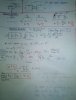
Doing some calculations, I recently reached a contradiction. I'm sure there must be an error in some step.
Input impedance of a basic opamp inverting amplifier is given by input resistor (Zin = Rin).
Gain, by ratio of feedback by input resistor.
I treated this circuit as a shunt-shunt negative feedback, and did some calculations, which gave a much lower input impedance.
In shunt-shunt configuration, close-loop input impedance is given by Zin / (1 +AB).
Based on this assumptions, I see a contradiction.
Zin or Zin/(1+AB) ??
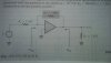