Continue to Site

Welcome to our site!

Electro Tech is an online community (with over 170,000 members) who enjoy talking about and building electronic circuits, projects and gadgets. To participate you need to register. Registration is free. Click here to register now.

  • Welcome to our site! Electro Tech is an online community (with over 170,000 members) who enjoy talking about and building electronic circuits, projects and gadgets. To participate you need to register. Registration is free. Click here to register now.

interfacing stepper motor with 8051

Status
Not open for further replies.
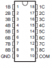
iam using 89S52 wit ULN2803A to drive a stepper motor
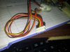
iam confused about the connection the stepper motor iam using is shown in the attached picture here

my code


#include<reg51.h>


void delay(unsigned int count)
{
int i,j;
for(i=0;i<count;i++)
for(j=0;j<1275;j++); // delay about a milli sec
}

void main()
{
while(1)
{
P2=0x01; // uln2803a connected to port 2
delay(10);
P2=0x03;
delay(10);
P2=0x02;
delay(10);
P2=0x06;
delay(10);
P2=0x04;
delay(10);
P2=0x0C;
delay(10);
P2=0x08;
delay(10);
P2=0x09;
delay(10);
}
}

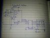
here is the circuit iam following in the attached pics

problem here is stepper motor do not revolve but when i simulate it in the proteus software with ULN2003A instead of ULN2803A it works fine

when doing it on hardware when i forcefully try to revolve the stepper motor it resist (vibrate)..
any one please make me correct
 

Attachments

  • upload_2014-10-31_18-32-35.png
    upload_2014-10-31_18-32-35.png
    4.5 KB · Views: 470
  • upload_2014-10-31_18-32-58.jpeg
    upload_2014-10-31_18-32-58.jpeg
    1.3 MB · Views: 510
  • 20141101_112234.jpg
    20141101_112234.jpg
    68.8 KB · Views: 1,498
Last edited:
i have read plenty of tutorials but the problem is still same..
i dont know.. weather the orientations of the wire attached to ULN pin is wrong or the circuit i followed is wrong but it seems to be right
 
should i also have to use seprate ground for the stepper motor driving ic(ULN2803) and the microcontroller??

last time when i did make the ground common for both ULN and Microcontroller the axle rotate a single step forward then a single step backward and so on.. back and forth
but it does not rotates fully clockwise or anticlockwise
 
If you are unsure about the connections.. You can use a multimeter to find out... A and B = res... C and D = res

Then find half the resistance A and B to com1 the C and D to com2 Usually they are wired

A.. C1.. B.. C.. C2.. D..
 
I have just got this working with the ULN2803.... The outputs are inverted so you need to invert your driver code.

Instead of ..
0x0A, 0x08, 0x09, 0x01, 0x05, 0x04,0x06,0x02

I had to use..
0x05, 0x07, 0x06, 0x0E, 0x0A, ox0B, 0x09, 0x0D
 
I have just got this working with the ULN2803.... The outputs are inverted so you need to invert your driver code.

Instead of ..
0x0A, 0x08, 0x09, 0x01, 0x05, 0x04,0x06,0x02

I had to use..
0x05, 0x07, 0x06, 0x0E, 0x0A, ox0B, 0x09, 0x0D

have u used the same circuit iam using for this..if there is any changes then please let me know
 
No! I have used the values I use...

Code:
void main()
  {
  while(1)
    {
    P2=0x05; // uln2803a connected to port 2
    delay(10);
    P2=0x07;
    delay(10);
    P2=0x06;
    delay(10);
    P2=0x0E;
    delay(10);
    P2=0x0A;
    delay(10);
    P2=0x0B;
    delay(10);
    P2=0x09;
    delay(10);
    P2=0x0D;
    delay(10);
    }
  }

If your motor doesn't turn, just check your wiring.... A1 = P2.0.. A2 = P2.2... B1= P2.3 and B2 = P2.1
 
I have just got this working with the ULN2803.... The outputs are inverted so you need to invert your driver code.

Instead of ..
0x0A, 0x08, 0x09, 0x01, 0x05, 0x04,0x06,0x02

I had to use..
0x05, 0x07, 0x06, 0x0E, 0x0A, ox0B, 0x09, 0x0D

THANKS FOR YOUR CONCERN SIR..

i just want to ask a question that is there any relation between the value you selected and the values i was working with..
i mean to say how did u calculated these values ?
what is the logic behind these values that you have given to me?
it will help me a lot if u answer me
 
There is no logic..

You need to turn the motors... If you common the motors with a positive ie.. 12v then you need to ground out the windings in a specific order....

If you connect A to pin 0 and A' to pin 2
Then connect B to pin 1 and B' to pin 3

You need to ground (via the ULN ) the windings you need to excite..
so instance 1

Pin0 = LOW = A'
Pin1 = HIGH = B'
Pin2= LOW = A
Pin3 = HIGH = B

So put 0x0A on the port... if you need to rotate CCW then swap the pins to suit... If you look at the picture in the tutorial it explains the sequence in great detail..

motor-schematics-png.85609


If you want "Half Steppping" then insert a single step in between the values... 1010 (0x0A) to 1001 ( 0x09) you can see that bit 1 moves to bit 0, so omit this bit and inset that value 1010 -- 1000 -- 1001.... If the motor has issues ie doesn't turn or wobbles.. You need to increase the delay between steps or swap one of the motor pairs A for A' or B for B'....

sorry iam a noob here still cant understand

i did understand fully what iam doing previously.. i mean i did understand the significance of the values( 0x0A, 0x08, 0x09, 0x01, 0x05, 0x04,0x06,0x02) which i am previously using.. i know how the work..

but the values u suggested and the statement u r making here.. confusing me

in every tutorial i have seen the same values i have taken, thus i know the significance of it... but the driving ic is not the uln2083a, which may make me in choosing those values i have taken previously

and sorry for the bad english

if u give some more detail.. that will definitely work for me!
 
Last edited:
Sorry about the confusion...... If you are using the sequence 0x0A ~ 0x02 and it works.. Then why did you use a different sequence in your first post..... 0x01, 0x03,0x02,0x06,0x04,0x0C,0x08,0x09... This implies that you have wired the stepper different to me.. It's still the same sequence but the windings are connected...

I use 0,1,2,3 for B', A', B, A
You use 0,1,2,3 As A, B, A', B'

So the motor will behave exactly the same....

i have used this sequence 0x01, 0x03,0x02,0x06,0x04,0x0C,0x08,0x09..
and its not working..
but i have seen many tutorials which have used the same sequence

however this sequence is working on the simulation software that is proteus, with the same connections which i did on simulation it does'nt work on hardware...

but theoretically i think iam right

A, B, A',B' is confusing to me

as u seen in my circuit diagram i have marked the wire sequence as A B C D and the connection iam using is shown in the image that i attached
 
Status
Not open for further replies.

Latest threads

New Articles From Microcontroller Tips

Back
Top