Continue to Site

Welcome to our site!

Electro Tech is an online community (with over 170,000 members) who enjoy talking about and building electronic circuits, projects and gadgets. To participate you need to register. Registration is free. Click here to register now.

  • Welcome to our site! Electro Tech is an online community (with over 170,000 members) who enjoy talking about and building electronic circuits, projects and gadgets. To participate you need to register. Registration is free. Click here to register now.

Interfacing PIC 16F628A to a modem

Status
Not open for further replies.

TeleStudent

New Member
Hello everybody, i would like some help in doing my project and it is basically a PIC ( 16F628A) interfaced to a GSM modem (WAVECOM FASTRACK M1306B ) where i will use the AT commands to send (only) a simple SMS to a phone number.

the problem is that i can not seem to get the AT commands to be sent from the PIC to the GSM modem and in order to identify the problem i did the following steps:

1- Check the connections and voltage drop in every important pin and everything turned out fine.

2- Test the GSM modem by connecting it the PC using hyperTerminal and i was able to send SMS to my phone.

3- After programming my PIC to send the AT commands i connected my circuit to my computer ( PIC 16F628A + MAX232) using hyperTerminal and it showed everything as expected.

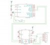
and below is the schematic and the code of my project.

NOTE:my GSM modem has a VGA port so the person that provided me the GSM modem gave me a cable that converts the VGA connection to a RS232 DB 9 (Female) connection.

(I am using MikroC Compiler )

Code:
void main(){
CMCON = 7;                          //Disable Comparators
UART1_init(9600);                   //Initiate baud rate to 9600
Delay_ms(100);                      //Delay 1 second
UART1_Write_Text("AT+CMGF=1");       //Write "AT+CMGF=1"
UART1_Write(0x0D);                  //<CR> mean (ENTER)
Delay_ms(100);						//Delay
UART1_Write_Text("AT+CMGS=");       //Write "AT+CMGS="
UART1_Write(0x22);                  //Write (")
UART1_Write_Text("xxxxxxxxxxxx");  //Number SMS send to
UART1_Write(0x22);                  //Write (")
UART1_Write(0x0D);                  //<CR> mean (ENTER)
Delay_ms(100);                      //Delay
UART1_Write_Text("hi");             //Words to be sent
UART1_Write(26);                    //Write "ctrl+z"
Delay_ms(100);                      //Delay
}
 

Attachments

  • New.jpg
    New.jpg
    98.3 KB · Views: 526
Last edited:
Connect the modem to the PC with the cables provided.. Access the register in the modem, and see if you can disable hardware handshaking... If not you need to connect RTS & CTS on the modem side ( pins 7 & 8 of the 9 pin connector ).
 
By the way,i found a piece of info on the web and i really appreciate it if you help me verify its contents.

For references purposes : It is quoted from "Laktronics" from "edaboard.com" forums.

interfacing gsm modem to microcontroller
Hi,
I suggest you to remove the present connections to pins 4 and 7 of the 9 pin connector. Then:
1. You short pins 4 and 7 of the connector and connect to pin 7 of Max 232 IC .
2. Connect pin 10 of Max 232 to ground.
3. You also connect pin 8 of Max 232 to Vcc through 1K resistor.

Points 1 and 2 ensures that DTR and RTS will be enabled high (10V) if your modem looks for that for communication. This will ensure that the status of PC's connector pins match with your controller connector. Point No.3 is just to ensure that the rx gate is not left open.

In one of the recent discussions in the Forum, it was pointed out that MAX 232 should use all 1uF capacitors only in the place of 10uF caps used to be seen with some of the earlier designs. I am not sure how far the value of these caps will affect, however, it is true that all recent data sheets of Maxim/TI etc. show only 1uF capacitors.

Also, with these changes, you can connect your microcontroller card using a cross connected cable to PC and check if it works with hyper terminal under identical condition of Baud rate etc., which you used while connecting PC to the modem. It will ensure that your micro is working as expected.

Please give us your test results.

Regards,
Laktronics
 
What GSM modem do you have? Most modems are hardware handshake by default ie... all 9 pins of the 9 pin connector are used... If you need to connect it with only three wires then you must configure the modem on the PC first.. most modems use the standard AT command set to change internal settings ie... ATS0 = register 0 ATS1 register 1 and so on.

This way you can change baud rates and such... Have you got the datasheet?
 
Still it does not work even after i change "the local flow control" to (0,0)..do u have any other suggestions ? ...i really appreciate your help and could you check the code and the schematic above.
 
Just connect pins 7 and 8 on the 9 pin connector. Sometimes there is a "saving" feature... any changes applied will only take effect after writing to this register. I don't really relish reading the entire document. As its only this issue your having, just connect the two pins.
 
You say it works with hyperterminal? You can send an SMS to a mobile phone when connected to the PC?

Then what happens when you connect the PC directly to the pic? Can the PC read the pic?....If so then you are connecting the modem up incorrectly... A modem is connected as a DTE which means rx is connected to rx and tx to tx, I suspect you have it connected null modem (means NOT modem ) swap pins 2 and 3 on the pic board...When you connect to a PC you'll need to swap it back.
 
Status
Not open for further replies.

Latest threads

New Articles From Microcontroller Tips

Back
Top