Continue to Site

Welcome to our site!

Electro Tech is an online community (with over 170,000 members) who enjoy talking about and building electronic circuits, projects and gadgets. To participate you need to register. Registration is free. Click here to register now.

  • Welcome to our site! Electro Tech is an online community (with over 170,000 members) who enjoy talking about and building electronic circuits, projects and gadgets. To participate you need to register. Registration is free. Click here to register now.

interfacing multiple feild sensors with microcontroller.

Status
Not open for further replies.
Thanks all for your time......

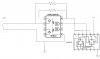
I'm thinking six edge-triggered flip-flops (like the 74HC175) to capture and store an edge event. Present the output of the flip-flops to your I/O pins directly, or follow with a multiplexer so that you can identify and route the stored event into one of 3 interrupts.

Not a bad idea.....but how do i proceed with the interfacing multiple trigger pulse source to the 74HC175.

What will be the input to the flip flop data pin?. And also identifing the input source at the multiplexer is a grey area?

hope current loop 4-20ma will help me get that pulse over long distance.

davidbeardavidbear said:
You might try putting a 555 timer used as a "one shot" on each button so that the PIC will see the initial signal as an interrupt, and then have enough time to poll which timer is still high.

I didn't understand this part.

Thanks all once again........
 
Last edited:
Thanks for your time...

I missed the fact you were using a 16F628. However the 628 also has interrupt on change on the top 4 bits of port b and so could be used to read 4 push buttons. With a bit of ingenuity you can easily make an array of 4*4 switches produce an interrupt when 1 or more are pushed.

Maybe you should explain what you are trying to do as push buttons are normally so slow that polling would be easily fast enough.

Mike.

this will involve the interrupt pin and an I/O isn't.
Like this attached..

With pts A and B connected to the INT pin , One end of 1&2 connected to Vcc and the other end connected to the I/O pin if switches are involved.

Here i may have to check the corresponding I/O line when INT is triggered isn't.
 

Attachments

  • Doc1.doc
    395 KB · Views: 140
Attached is an example of one channel. OR gate the INT outputs from all channels to generate an interrupt from any channel. Connect the INT outputs from each channel to a multiplexer. The output of the multiplexer goes to an I/O pin (set as an input). The channel select inputs of the multiplexer go to I/O pins (set at outputs). Your interrupt service routine reads the output of the multiplexer while your channel select output scans to determine which channel generated the interrupt. Use an I/O pin (set as output) to clear the flip-flops once the service routine is completed.

Be aware that the flip-flop will not be trigger again until the sensor switch is opened and closed again. If the sensor remains closed after servicing it, the job is done, until it opens and closes again.
 

Attachments

  • Drawing1.jpg
    Drawing1.jpg
    556.6 KB · Views: 180
Last edited:
You could wire OR the switches via diodes to an interrupt input. The ISR then reads the switch inputs to determine which switch is active. This would also detect multiple switch/input closures.
 
Just use the IOC feature of the chip. You connect your 4 push buttons to PortB 4-7 and when ever a button is pressed it will cause an interrupt. The reason they added this function is so you didn't need extra chips/diodes, whatever.

Just try it. When you get stuck, come back and we will help you out.

Mike.
 
Thanks all for your time.....

Lot of ideas to work this week....i will surely let you guys know when done with the trails.

Thanks.
 
Status
Not open for further replies.

Latest threads

New Articles From Microcontroller Tips

Back
Top