Continue to Site

Welcome to our site!

Electro Tech is an online community (with over 170,000 members) who enjoy talking about and building electronic circuits, projects and gadgets. To participate you need to register. Registration is free. Click here to register now.

  • Welcome to our site! Electro Tech is an online community (with over 170,000 members) who enjoy talking about and building electronic circuits, projects and gadgets. To participate you need to register. Registration is free. Click here to register now.

Interfacing a relay with microcontroller

Status
Not open for further replies.

trojan89

New Member
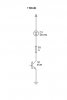
Thank you guys for all the support till now. But have run into a problem while interfacing the micro controller with a relay. I am the using the circuit shown below
**broken link removed**

link:"http://static.electro-tech-online.com/imgcache/1038-15.gif"

When I measure the output across the diode without the relay i have 12V when the PIC goes high and 0V when PIC is low. But when I connect the relay across the diode, the voltage immediately drops to around 5V regardless of whether PIC is high or low. What am I doing wrong? And how do I remedy it?

As always thanks in advance.
 
How much current does the relay draw? What's the coil resistance?


Try reducing the base resistor to 1k.
 
Hi,

You do not give the specs for the transistor or relay, it does sound like a wrong part or connection.

To check things, go back one step and test the pic and transistor work ok with a led.
 

Attachments

  • led..jpg
    led..jpg
    4.7 KB · Views: 576
try to add a resistor to the Transistor's output connected to the +12 Volts.... in your circuit the transistor is NOT well connected
 
How much current does the relay draw? What's the coil resistance?


Try reducing the base resistor to 1k.

Thanks a ton. Now the relay latches, but the switch off voltage is still high enough to weakly keep the relay latched. Will a resistor in series with the diode solve the problem?( The ON voltage will still be high enough and it will decrease the OFF voltage)
 
Thanks a ton. Now the relay latches, but the switch off voltage is still high enough to weakly keep the relay latched. Will a resistor in series with the diode solve the problem?( The ON voltage will still be high enough and it will decrease the OFF voltage)

No, a resistor in series with the diode will only prevent it doing it's job correctly.

It's not very clear what you're actually describing - but place a 1K resistor from base to emitter of the transistor as well, the resistor from RB6 to ground is pretty pointless.
 
I think he's talking about adding a resistor so the relay turns off more quickly?

It can be done but the resistor needs to be low enough to keep the voltage below the transistor's maximum rating. If the resistor has the same resistance as the relay's coil, the back-EMF will be equal to the supply voltage.

Adding a suitable resistor will increase the life of the relay but it will work without the resistor.

I am using BC547b transistor and an IN4007 diode. What resistor value would you recommend? The relay resistance is 200ohm
 
Sorry for any confusion caused.

Just to be clear; you don't need a resistor, it's just an optional extra to increase the life of the relay.
 
When you said you are getting 5V across the diode when the relay is connected no matter whether the PIC pin is HIGH or LOW, it means the transistor is ON (but not saturated, which is required to turn the relay ON) in both cases. If you have an additional BC547C transistor, I would suggest you to use the Darlington configuration for driving the relay. Just use one 10K resistance between the PIC pin and the base input. Remove the another 10K resistor. This should work.
- Raj
 
Hang on... Am I missing something here... (watching Relocation Relocation). If the collector voltage is always at 5V then the transistor is not turning off. Is the transistor in correctly? It is obviously working cos you are getting 12V and 0V when the transistor is switching.

When the load voltage is 5V what is the voltage on the base of the transistor (wrt to 0V). Is the transistor turning off (base is at 0V)?

You could try replacing the relay coil with a 200 Ohm resistor to simulate the relay coil to see if the transistor will drive the current.

I also cannot see how adding any resistors anywhere will increase the life of the relay. the only resistor you need is in the base of the transistor and this should be about 1k. No higher. remove the 10k resistor from the port to ground.

You also do not need the 4MHz crystal - you might as well use the internal clock unless you want a precision clock


Let me know what you find...
 
Status
Not open for further replies.

Latest threads

New Articles From Microcontroller Tips

Back
Top