Continue to Site

Welcome to our site!

Electro Tech is an online community (with over 170,000 members) who enjoy talking about and building electronic circuits, projects and gadgets. To participate you need to register. Registration is free. Click here to register now.

  • Welcome to our site! Electro Tech is an online community (with over 170,000 members) who enjoy talking about and building electronic circuits, projects and gadgets. To participate you need to register. Registration is free. Click here to register now.

Interface problem

Status
Not open for further replies.

andy257

Member
Hi All,

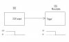
Trying to interface an active low output to an active low input. Sounds easy but the output from the GPIo is 3.3V and the input to the circuit is ran from 12V supply. Since the 555 is negative edge triggered i dont think i can use a NPN transistor or the transistor will always be on. I am a little wary of using a pull up on the 3.3V line as i dont know if it can handle 12V.


Anyone suggest an easy way to interface the two?

Thanks
 

Attachments

  • trigger.jpg
    trigger.jpg
    10.2 KB · Views: 151
I believe you can do this using a simple comparator (LM393) **broken link removed**.
Just set voltage reference to under 3.3V.

Mike
 
Last edited:
This would work but at switch on you get a false trigger.

Potential divider on non-inverting side and 3.3V on inverting side. The two pieces of kit power up slightly ahead of one another and i get some kind of race condition which puts the 555 into a constant trigger loop.


Are there any alternatives to the 555 timer? Interfacing two different voltages is too difficult with the 555.
 
NO, it's easy. The 555 provides a "Control Voltage" pin (pin 5) that allows you to program the threshold. I believe you can just connect this to 3.3v (someone correct me if I'm wrong)

EDIT: Looking at the datasheet, I think you need to connect a lower voltage to pin 5. Connect the voltage at which you want the timer to terminate the output.
 
Last edited:
I am using the 555 as a monostable. Therefore i think i have to ground pin 5 through a small cap.
 
Please see Edit to post #4. I would divide the 3.3V and connect to pin 5 thru a CE configured general purpose transistor (3904) I've never tried this, but I see no reason why it wouldn't work.
 
So how does it work this control pin? There doesnt seem much info on the web or any examples of how to use it.

I think i have not made myself clear enough. The input is being used to reset a circuit driven by the 555. The output from the 555 drives a relay which controls the power to another device. When the 3.3V output goes low i want to trigger the relay and after say 5 seconds close the relay. I wouldnt have a problem if the output was active high but since its active low its causing problems.

Also the two circuits are driven from two different voltages. The 555 has a pull up pin on the trigger terminal connected to 12V. The output from the SBc is only 3.3V.
 
Last edited:
Sorry, I got sidetracked. In "normal" operatoin, the reference voltage is derived from the rail with a trio of resistors that divide the rail to VCC*2/3 for the "threshold" and to VCC*1/3 for the trigger voltage. If you use the control pin, you replace VCC at the threshold with your control voltage, Vc. And Vc/2 for the trigger. So, suppose you use 3.3V divided to 2/3 for the control pin, or 2.2V. Then the trigger will be 3.3V*2/3*1/2, or 3.3V*1/3, which is 1.1V. The way I would do it is to use a voltage divider for the 2/3, say a 33K and 66K ( or whatever standard resistors are the closest). Connect that to a CE configured transistor, and the output to the control pin. Now, you have 3.3*2/3 connected to the threshold, and all the math above holds.
 
Last edited:
Status
Not open for further replies.

New Articles From Microcontroller Tips

Back
Top